Ford Explorer: Supplemental Restraint System / Removal and Installation - Front Door Side Impact Sensor
Removal
.jpg) WARNING:
The following procedure prescribes critical repair steps
required for correct restraint system operation during a crash. Follow
all notes and steps carefully. Failure to follow step instructions may
result in incorrect operation of the restraint system and increases the
risk of serious personal injury or death in a crash.
WARNING:
The following procedure prescribes critical repair steps
required for correct restraint system operation during a crash. Follow
all notes and steps carefully. Failure to follow step instructions may
result in incorrect operation of the restraint system and increases the
risk of serious personal injury or death in a crash.
NOTE: LH (left hand) side shown, RH (right hand) similar.
NOTE: Removal steps in this procedure may contain installation details.
-
Refer to: Pyrotechnic Device Health and Safety Precautions (100-00 General Information, Description and Operation).
WARNING:
Before beginning any service procedure in this
manual, refer to health and safety warnings in section 100-00 General
Information. Failure to follow this instruction may result in serious
personal injury.
-
Depower the SRS.
Refer to: Supplemental Restraint System (SRS) Depowering (501-20 Supplemental Restraint System) .
-
Remove the front door trim panel.
Refer to: Front Door Trim Panel (501-05 Interior Trim and Ornamentation, Removal and Installation).
-
Remove the front door side impact sensor.
-
Disconnect the electrical connector.
-
Remove the bolts.
Torque: 22 lb.in (2.5 Nm)
-
Remove the front door side impact sensor.
-
Disconnect the electrical connector.
.jpg) |
Installation
-
NOTE: The front door side impact sensor mating surfaces must be smooth and allow for a flush attachment to each other.
To install, reverse the removal procedure.
-
Repower the SRS.
Refer to: Supplemental Restraint System (SRS) Repowering (501-20 Supplemental Restraint System) .
 Removal and Installation - Driver Knee Airbag
Removal
WARNING:
The following procedure prescribes critical repair steps
required for correct restraint system operation during a crash. Follow
all notes and steps carefully...
 Removal and Installation - Front Impact Severity Sensor
Removal
WARNING:
The following procedure prescribes critical repair steps
required for correct restraint system operation during a crash. Follow
all notes and steps carefully...
Other information:
Ford Explorer 2020-2024 Service Manual: Description and Operation - High Voltage System Health and Safety Precautions - Overview
WARNING: Service of the high voltage system on this vehicle is restricted to qualified personnel. The required qualifications vary by region. Always observe local laws and legislative directives regarding electric vehicle service. Failure to follow this instruction may result in serious personal injury or death...
Ford Explorer 2020-2024 Owners Manual: Roof Racks and Load Carriers (If Equipped)
WARNING: When loading the roof racks, we recommend you evenly distribute the load, as well as maintain a low center of gravity. Loaded vehicles, with higher centers of gravity, may handle differently than unloaded vehicles. Take extra precautions, such as slower speeds and increased stopping distance, when driving a heavily loaded vehicle...
Categories
- Manuals Home
- 6th Generation Explorer Owners Manual
- 6th Generation Explorer Service Manual
- Diagnosis and Testing - Parking Brake - Vehicles With: Electric Brake Booster
- Engine - 2.3L EcoBoost (201kW/273PS)
- General Procedures - Rear Camber Adjustment
- New on site
- Most important about car
Windshield Wipers
 Push the lever up or down to operate
the windshield wipers.
Push the lever up or down to operate
the windshield wipers.
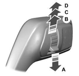
A - Single wipe.