Ford Explorer: Glass, Frames and Mechanisms / Description and Operation - Glass, Frames and Mechanisms - System Operation and Component Description
System Operation
System Diagram - Power Windows
Front Power Windows
.jpg)
.jpg)
| Item | Description |
|---|---|
| 1 | Driver Window Control Switch |
| 2 | Driver Door Window Regulator Motor |
| 3 | PDM |
| 4 | Passenger Door Window Control Switch |
| 5 | MS-CAN |
| 6 | LIN |
| 7 | DDM |
| 8 | Passenger Door Window Regulator Motor |
Network Message Chart - Front Power Windows
Passenger Door Module (PDM) Network Input Messages
| Broadcast Message | Originating Module | Message Purpose |
|---|---|---|
| Passenger window command | DDM | When activating the front passenger window from the driver window control switch, the passenger window command is sent from the DDM to the PDM. |
System Diagram - Rear Window Defrost
.jpg)
.jpg)
| Item | Description |
|---|---|
| 1 | BJB |
| 2 | HVAC |
| 3 | MS-CAN |
| 4 | Rear Window Defrost Grid |
| 5 | GWM |
| 6 | BCMC |
| 7 | HS-CAN1 |
Network Message Chart - Rear Window Defrost
BCMC Network Input Messages
| Broadcast Message | Originating Module | Message Purpose |
|---|---|---|
| Rear window defrost request | HVAC module | When the BCMC receives the rear window defrost request message, the BJB activates the rear window defrost system. |
Delayed Accessory Power
Voltage is supplied to the power window system by the accessory delay relay, located in BCM. The accessory delay relay is integral to the BCM and cannot be serviced separately. The BCM activates the accessory delay relay whenever the ignition is on, or whenever the ignition is changed from on to off while the LH and RH front doors are closed.
The BCM deactivates the accessory delay relay when:
- the LH or RH front door is ajar and the ignition is off.
- ten minutes have elapsed since the ignition status has changed from on to the off position.
Front Power Window Operation
NOTE: If the battery is disconnected while the window is moving, the one-touch up and one-touch down feature (and obstacle detection) is disabled prior to initialization.
Refer to: Power Door Window Initialization (501-11 Glass, Frames and Mechanisms, General Procedures).
The power windows operate when the accessory delay relay is active. Both front windows are equipped with obstacle detection and one-touch up and one-touch down functionality. If an obstacle has been detected in the window opening as the window glass is moving upward, the window regulator motor automatically reverses direction and moves the window glass downward.
Driver Front Window Operation
The driver window control switch communicates to the DDM through a private LIN. When commanded by the driver window control switch, the DDM supplies power and ground to operate the driver front window in the desired direction. The DDM monitors fluctuations of the motor current (ripple count for DC motors) to determine the window glass position.
Passenger Front Window Operation
The driver window control switch communicates to the DDM through a private LIN. The DDM communicates to the PDM through the MS-CAN. When commanded by the driver window control switch or the passenger front door window control switch, the PDM supplies power and ground to operate the passenger front door window glass in the desired direction. The PDM monitors fluctuations of the motor current (ripple count for DC motors) to determine the window glass position.
Rear Door Window Operation
The rear door window control switches contain 2 relays which, when at rest (inactive), provide a ground path to their respective window regulator motor circuit(s). The rear door window control switches receive voltage (high current circuit) from the accessory delay relay whenever it is active. When the rear door window control switches receive a voltage signal from the driver door window control switch and/or when the rear door window control switch is activated, the rear door window control switch supplies high current voltage (and ground) to operate the window regulator motor in the desired direction.
Passenger Windows Lockout
When the lockout switch (part of the driver window control switch) is in the LOCK position, the rear passenger windows only operate from the driver window control switch.
Rear Window Defrost
The rear window defrost system only operates when the engine is running. When the rear window defrost switch is activated, the HVAC module sends the request message to the BCMC (integral to the BJB). The BJB activates the rear window defrost relay (integral to the BJB). When the rear window defrost relay is activated, the rear window defrost grid(s) are energized. In some cases, the rear window defrost system may automatically activate as an extra load for accelerated engine warm-up. However the rear window defrost status LED remains off unless the rear window defrost switch is activated.
The BCMC deactivates the rear window defrost relay when any of these conditions is met:
- The rear window defrost switch is pressed when the feature is active.
- Ignition state is changed from on to off.
- A predetermined timer completes.
- Battery voltage has dropped below a specified threshold (load management strategy).
Component Description
BCM
The BCM controls the accessory delay relay. PMI is required whenever installing a new module.
BCMC
When a rear window defrost request message is sent to the BCMC, the BCMC sends a request to the BJB through a LIN to activate the rear window defrost system. PMI is required whenever installing a new module.
Driver Door Module (DDM)
The DDM receives power window commands from the driver window control switch and the driver side rear door window control switch. The DDM supplies voltage and ground to operate the driver side front and rear power window regulator motors.
The DDM also communicates driver window control switch requests to the PDM through the MS-CAN. PMI is required whenever installing a new module.
Driver Window Control Switch
The driver window control switch receives voltage whenever the accessory delay relay is active. The driver window control switch communicates to the DDM through a private LIN.
The driver window control switch supplies low current voltage signal through momentary contacts to activate the internal relays within each of the rear passenger window control switches to operate the rear windows.
Front Passenger Door Window Control Switch
The front passenger door window control switch contains momentary contacts (one for each window switch direction). The PDM provides a return (ground) for the front passenger door window control switch. When the control switch is activated, a ground signal is supplied to the PDM to operate the window motor in the desired direction.
HVAC Module
The HVAC module contains the rear window defrost switch. PMI is required whenever installing a new module.
Passenger Door Module (PDM)
The PDM receives power window commands from the passenger front door window control switch or from the DDM through the MS-CAN. The PDM supplies voltage and ground to operate the passenger front and rear power window regulator motors. PMI is required whenever installing a new module.
Rear Passenger Door Window Control Switch
Each of the rear door window control switches contains momentary contacts (one for each window switch direction). The DDM or PDM provides a return (ground) for the rear door window control switch. When the control switch is activated, a ground signal is supplied to the DDM or PDM to operate the window motor in the desired direction.
Window Regulator Motor
The window regulator motor(s) are bi-directional. Window direction is determined by the polarity of the voltage being supplied to the motor from the associated door module.
 Description and Operation - Glass, Frames and Mechanisms - Overview
Overview
Power Window Operation
Standard power window features include one-touch up and one-touch down (front doors only). The window control switch:
raises or lowers all windows from the d..
 Diagnosis and Testing - Glass, Frames and Mechanisms
Diagnostic Trouble Code (DTC) Chart
Diagnostics in this manual assume a certain skill level and knowledge of Ford-specific diagnostic practices. REFER to: Diagnostic Methods (100-00 General Informati..
Other information:
Ford Explorer 2020-2026 Service Manual: Removal and Installation - Wheel Studs
Special Tool(s) / General Equipment Hydraulic Press Removal NOTICE: Suspension fasteners are critical parts that affect performance of vital components and systems. Failure of these fasteners may result in major service expense. Use the same or equivalent parts if replacement is necessary...
Ford Explorer 2020-2026 Owners Manual: SelectShift Automatic™ Transmission
Your vehicle is equipped with a SelectShift Automatic transmission, which gives you the ability to change gears up or down (without a clutch) as desired. In order to prevent the engine from running at too low an RPM, which may cause it to stall, SelectShift still automatically makes some downshifts if it has determined that you have not downshifted in time...
Categories
- Manuals Home
- 6th Generation Explorer Owners Manual
- 6th Generation Explorer Service Manual
- Electric Parking Brake
- Interior Trim and Ornamentation
- Engine
- New on site
- Most important about car
Windshield Wipers
 Push the lever up or down to operate
the windshield wipers.
Push the lever up or down to operate
the windshield wipers.
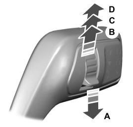
A - Single wipe.