
Ford Explorer: Exterior Lighting / Removal and Installation - Light Emitting Diode (LED) Control Module
Ford Explorer 2020-2026 Service Manual / Electrical / Lighting / Exterior Lighting / Removal and Installation - Light Emitting Diode (LED) Control Module
Removal
NOTE: Removal steps in this procedure may contain installation details.
-
Remove the headlamp assembly.
Refer to: Headlamp Assembly (417-01 Exterior Lighting, Removal and Installation).
-
Remove the bolts and position the LED control module.
 |
-
Disconnect the electrical connectors and remove the LED control module.
 |
Installation
-
To install, reverse the removal procedure.
-
NOTE: Carry out this step only when a LED (light emitting diode) headlamp module is being replaced.
Using a diagnostic scan tool, perform the BCM - LIN New Module Initialization. Follow the diagnostic scan tool directions.
 Removal and Installation - High Mounted Stoplamp
Removal
NOTE:
Removal steps in this procedure may contain installation details.
Remove the rear spoiler.
Refer to: Rear Spoiler (501-08 Exterior Trim and Ornamentation, Removal and Inst..
 Removal and Installation - Light Sensor
Special Tool(s) /
General Equipment
Interior Trim Remover
Removal
NOTE:
Removal steps in this procedure may contain installation details...
Other information:
Ford Explorer 2020-2026 Service Manual: Description and Operation - Steering Column - System Operation and Component Description
System Diagram Item Description 1 DDM 2 SCCM 3 Memory set switch 4 DSM 5 BCM 6 MS-CAN 7 HS-CAN2 8 Steering column control switch 9 Steering column tilt motor 10 Hall effect sensor 11 GWM 12 Steering column telescopic motor 13 Hall effect sensor 14 HS-CAN1 Sys..
Ford Explorer 2020-2026 Service Manual: General Procedures - Module Programming
Check NOTE: Perform the following pre-checks to make sure module programming completes without errors. Start the programming session in KOEO. Make sure the vehicle battery is fully charged or is connected to a battery charger. The battery state of charge should be 12...
Categories
- Manuals Home
- 6th Generation Explorer Owners Manual
- 6th Generation Explorer Service Manual
- Traction Control
- General Procedures - Transmission Fluid Drain and Refill
- Removal and Installation - Front Halfshaft Speed Sensor
- New on site
- Most important about car
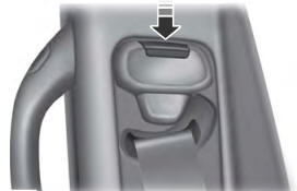
Seatbelt Height Adjustment
WARNING: Position the seatbelt height adjuster so that the seatbelt rests across the middle of your shoulder. Failure to adjust the seatbelt correctly could reduce its effectiveness and increase the risk of injury in a crash.

Copyright © 2026 www.foexplorer.com