Ford Explorer: Parking Brake and Actuation / Description and Operation - Parking Brake - Component Location
Ford Explorer 2020-2026 Service Manual / Chassis / Brake System / Parking Brake and Actuation / Description and Operation - Parking Brake - Component Location
.jpg)
| Item | Description |
|---|---|
| 1 | ABS module |
| 2 | Parking brake switch |
| 3 | Parking brake actuator motor (2 required) |
 Description and Operation - Parking Brake - Overview
Overview
The
parking brake system uses 2 switch activated, Electronic Control Unit
(ECU) controlled motors to apply and release the rear brake calipers...
 Description and Operation - Parking Brake - System Operation and Component Description
System Operation
System Diagram
E338887
*.sttxt {
visibility: hidden;
}
*.stcallout {
visibility: visible;
}
..
Other information:
Ford Explorer 2020-2026 Service Manual: General Procedures - Adaptive Learning Drive Cycle
Programming NOTE: Perform the adaptive learning drive cycle on a level road surface. Using the scan tool, clear the DTCs (Diagnostic Trouble Codes) and Transmission Adaptive Tables. Drive the vehicle until the engine and transmission reach normal operating temperature...
Ford Explorer 2020-2026 Service Manual: Removal and Installation - Radiator Grille Opening Panel
Removal NOTE: Removal steps in this procedure may contain installation details. Remove both the headlamps. Refer to: Headlamp Assembly (417-01 Exterior Lighting, Removal and Installation). Remove the Horn assembly. Refer to: Horn (413-06 Horn, Removal and Installation)...
Categories
- Manuals Home
- 6th Generation Explorer Owners Manual
- 6th Generation Explorer Service Manual
- Automatic Transmission - 10-Speed Automatic Transmission – 10R60
- Removal and Installation - Front Halfshaft Speed Sensor
- Description and Operation - Jacking and Lifting - Overview
- New on site
- Most important about car
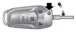
Integrated Keyhead Transmitter (If Equipped)
Use the key blade to start your vehicle and unlock or lock the driver door from outside your vehicle. The integrated keyhead transmitter functions as a programmed ignition key that operates all the locks and starts your vehicle, as well as a remote control.
Copyright © 2026 www.foexplorer.com