Ford Explorer: Bumpers / Removal and Installation - Front Bumper Cover
Ford Explorer 2020-2026 Service Manual / Body and Paint / Body and Paint / Bumpers / Removal and Installation - Front Bumper Cover
Special Tool(s) / General Equipment
| Interior Trim Remover |
Removal
NOTE: Removal steps in this procedure may contain installation details.
-
Remove the front wheels and tires.
Refer to: Wheel and Tire (204-04A Wheels and Tires, Removal and Installation).
-
On both sides.
Remove the screws, release the clips and position front fender moulding aside.
Use the General Equipment: Interior Trim Remover
Torque: 22 lb.in (2.5 Nm)
.jpg) |
-
On both sides.
Disconnect the front active park assist sensor electrical connector.
.jpg) |
-
On both sides.
Remove the fender liner push pins.
.jpg) |
-
On both sides.
Remove the screws.
Torque: 22 lb.in (2.5 Nm)
.jpg) |
-
Remove the screws.
Torque: 22 lb.in (2.5 Nm)
.jpg) |
-
On both sides.
Position the front fender liner aside.
.jpg) |
-
Disconnect the front bumper cover harness electrical connector.
.jpg) |
-
-
Disconnect the front bumper cover harness electrical connector.
-
Disconnect the front camera harness electrical connector.
-
Disconnect the washer hose.
-
Disconnect the front bumper cover harness electrical connector.
.jpg) |
-
On both sides.
Remove the front bumper cover to fender bolts and release the tab.
Torque: 35 lb.in (4 Nm)
.jpg) |
-
With the help of an assistant.
Remove the bolts, release the tabs, release the clips and remove the front bumper cover.
Torque: 22 lb.in (2.5 Nm)
.jpg) |
Installation
-
To install, reverse the removal procedure.
-
Vehicles equipped with 360° cameras only.
Align the 360° cameras.
Refer to: 360 Degree View Camera Alignment (413-13B Parking Aid - Vehicles With: Parking Aid Camera, General Procedures).
-
If replacing the front bumper cover.
Check the alignment of the front parking aid and front active park assist sensors.
Refer to: Azimuth System Check (413-13A Parking Aid - Vehicles With: Rear Parking Aid, General Procedures).
Refer to: Elevation System Check (413-13A Parking Aid - Vehicles With: Rear Parking Aid, General Procedures).
Refer to: Azimuth System Check (413-13C Parking Aid - Vehicles With: Active Park Assist, General Procedures).
-
If any sensor fails the check, diagnose the sensor fault.
Refer to: Parking Aid (413-13A Parking Aid - Vehicles With: Rear Parking Aid, Diagnosis and Testing).
Refer to: Parking Aid (413-13C Parking Aid - Vehicles With: Active Park Assist, Diagnosis and Testing).
 Removal and Installation - Front Bumper
Removal
Remove the front bumper cover.
Refer to: Front Bumper Cover (501-19 Bumpers, Removal and Installation).
With the help of assistant...
 Removal and Installation - Rear Bumper
Removal
NOTE:
Removal steps in this procedure may contain installation details.
All vehicles
Remove the rear bumper cover.
Refer to: Rear Bumper Cover (501-19 Bumpers, Removal and Inst..
Other information:
Ford Explorer 2020-2026 Service Manual: Removal and Installation - Front Fog Lamp
Removal NOTE: Removal steps in this procedure may contain installation details. Remove the front bumper cover. Refer to: Front Bumper Cover (501-19 Bumpers, Removal and Installation). NOTE: LH side shown, RH side similar...
Ford Explorer 2020-2026 Service Manual: Description and Operation - Message Center - System Operation and Component Description
System Operation System Diagram Item Description 1 RH steering wheel switch 2 PSCM 3 BCM 4 Door/liftgate ajar switches 5 GWM 6 SODR 7 Fuel pump and sender unit 8 IPC 9 APIM 10 Washer fluid level switch 11 Message center display 12 IPMA 13 Parking brake switch 14 ..
Categories
- Manuals Home
- 6th Generation Explorer Owners Manual
- 6th Generation Explorer Service Manual
- Fuel Filler Funnel Location & Running Out of Fuel
- Removal and Installation - Front Halfshaft Speed Sensor
- Auxiliary Power Points
- New on site
- Most important about car
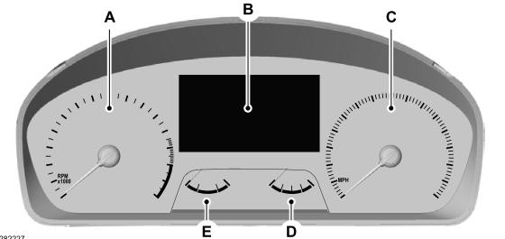
Gauges
4 Inch Display

A - Tachometer.
B - Information display.
C - Speedometer.
D - Fuel gauge.
E - Engine coolant temperature gauge.
Copyright © 2026 www.foexplorer.com
