Ford Explorer: Exterior Lighting / Diagnosis and Testing - Headlamps
Diagnostic Trouble Code (DTC) Chart
Diagnostics in this manual assume a certain skill level and knowledge of Ford-specific diagnostic practices.
REFER to: Diagnostic Methods (100-00 General Information, Description and Operation).
Diagnostic Trouble Code Chart
| Module | DTC | Description | Action |
|---|---|---|---|
| BCM | B14E0:11 | Exterior Lamps Power Supply "C": Circuit Short to Ground | GO to Pinpoint Test A |
| BCM | B14E0:15 | Exterior Lamps Power Supply "C": Circuit Short to Battery or Open | GO to Pinpoint Test A |
| BCM | B14E1:11 | Exterior Lamps Power Supply "D": Circuit Short to Ground | GO to Pinpoint Test A |
| BCM | B14E1:15 | Exterior Lamps Power Supply "D": Circuit Short to Battery or Open | GO to Pinpoint Test A |
| BCM | B14E2:11 | Exterior Lamps Power Supply "E": Circuit Short to Ground | GO to Pinpoint Test S |
| BCM | B14E2:15 | Exterior Lamps Power Supply "E": Circuit Short to Battery or Open | GO to Pinpoint Test S |
| BCM | B14E3:11 | Exterior Lamps Power Supply "F": Circuit Short to Ground | GO to Pinpoint Test S |
| BCM | B14E3:15 | Exterior Lamps Power Supply "F": Circuit Short to Battery or Open | GO to Pinpoint Test S |
| BCM | B14E5:01 | Left Front Enhanced Exterior Lighting System: General Electrical Failure | GO to Pinpoint Test B |
| BCM | B14E5:01 | Left Front Enhanced Exterior Lighting System: General Electrical Failure | GO to Pinpoint Test G |
| BCM | B14E5:08 | Left Front Enhanced Exterior Lighting System: Bus Signal / Message Failure | GO to Pinpoint Test B |
| BCM | B14E5:08 | Left Front Enhanced Exterior Lighting System: Bus Signal / Message Failure | GO to Pinpoint Test G |
| BCM | B14E5:1C | Left Front Enhanced Exterior Lighting System: Circuit Voltage Out of Range | GO to Pinpoint Test B |
| BCM | B14E5:1C | Left Front Enhanced Exterior Lighting System: Circuit Voltage Out of Range | GO to Pinpoint Test G |
| BCM | B14E5:49 | Left Front Enhanced Exterior Lighting System: Internal Electronic Failure | GO to Pinpoint Test B |
| BCM | B14E5:49 | Left Front Enhanced Exterior Lighting System: Internal Electronic Failure | GO to Pinpoint Test G |
| BCM | B14E5:55 | Left Front Enhanced Exterior Lighting System: Not Configured | GO to Pinpoint Test B |
| BCM | B14E5:55 | Left Front Enhanced Exterior Lighting System: Not Configured | GO to Pinpoint Test G |
| BCM | B14E5:61 | Left Front Enhanced Exterior Lighting System: Signal Calculation Failure | GO to Pinpoint Test B |
| BCM | B14E5:61 | Left Front Enhanced Exterior Lighting System: Signal Calculation Failure | GO to Pinpoint Test G |
| BCM | B14E7:01 | Right Front Enhanced Exterior Lighting System: General Electrical Failure | GO to Pinpoint Test B |
| BCM | B14E7:01 | Right Front Enhanced Exterior Lighting System: General Electrical Failure | GO to Pinpoint Test G |
| BCM | B14E7:08 | Right Front Enhanced Exterior Lighting System: Bus Signal / Message Failure | GO to Pinpoint Test B |
| BCM | B14E7:08 | Right Front Enhanced Exterior Lighting System: Bus Signal / Message Failure | GO to Pinpoint Test G |
| BCM | B14E7:1C | Right Front Enhanced Exterior Lighting System: Circuit Voltage Out of Range | GO to Pinpoint Test B |
| BCM | B14E7:1C | Right Front Enhanced Exterior Lighting System: Circuit Voltage Out of Range | GO to Pinpoint Test G |
| BCM | B14E7:49 | Right Front Enhanced Exterior Lighting System: Internal Electronic Failure | GO to Pinpoint Test B |
| BCM | B14E7:49 | Right Front Enhanced Exterior Lighting System: Internal Electronic Failure | GO to Pinpoint Test G |
| BCM | B14E7:55 | Right Front Enhanced Exterior Lighting System: Not Configured | GO to Pinpoint Test B |
| BCM | B14E7:55 | Right Front Enhanced Exterior Lighting System: Not Configured | GO to Pinpoint Test G |
| BCM | B14E7:61 | Right Front Enhanced Exterior Lighting System: Signal Calculation Failure | GO to Pinpoint Test B |
| BCM | B14E7:61 | Right Front Enhanced Exterior Lighting System: Signal Calculation Failure | GO to Pinpoint Test G |
| BCM | B1533:02 | Headlamp Switch Module: General Signal Failure | GO to Pinpoint Test A |
| BCM | B1533:08 | Headlamp Switch Module: Bus Signal / Message | GO to Pinpoint Test A |
| BCM | B1533:49 | Headlamp Switch Module: Internal Electronic Failure | GO to Pinpoint Test A |
| BCM | B1533:56 | Headlamp Switch Module: Invalid / Incompatible Configuration | GO to Pinpoint Test A |
| BCM | B1D00:11 | Left Low Beam: Circuit Short To Ground | GO to Pinpoint Test A |
| BCM | B1D00:15 | Left Low Beam: Circuit Short To Battery Or Open | GO to Pinpoint Test A |
| BCM | B1D01:11 | Right Low Beam: Circuit Short To Ground | GO to Pinpoint Test A |
| BCM | B1D01:15 | Right Low Beam: Circuit Short To Battery Or Open | GO to Pinpoint Test A |
| BCM | B1D02:11 | Left High Beam Circuit: Circuit Short To Ground | GO to Pinpoint Test S |
| BCM | B1D02:15 | Left High Beam Circuit: Circuit Short To Battery Or Open | GO to Pinpoint Test S |
| BCM | B1D03:11 | Right High Beam Circuit: Circuit Short To Ground | GO to Pinpoint Test S |
| BCM | B1D03:15 | Right High Beam Circuit: Circuit Short To Battery Or Open | GO to Pinpoint Test S |
| HCM | B1041:04 | Levelling Control: System Internal Failure | GO to Pinpoint Test H |
| HCM | B1041:54 | Levelling Control: Missing Calibration | GO to Pinpoint Test H |
| HCM | B1087:83 | LIN Bus "A": Value of Signal Protection Calculation Incorrect | GO to Pinpoint Test C |
| HCM | B1087:86 | LIN Bus "A": Signal Invalid | GO to Pinpoint Test C |
| HCM | B1088:83 | LIN Bus "B": Value of Signal Protection Calculation Incorrect | GO to Pinpoint Test C |
| HCM | B1088:86 | LIN Bus "B": Signal Invalid | GO to Pinpoint Test C |
| HCM | B1437:01 | Left Levelling Actuator: General Electrical Failure | GO to Pinpoint Test I |
| HCM | B1437:87 | Left Levelling Actuator: Missing Message | GO to Pinpoint Test G |
| HCM | B1439:01 | Right Levelling Actuator: General Electrical Failure | GO to Pinpoint Test I |
| HCM | B1439:87 | Right Levelling Actuator: Missing Message | GO to Pinpoint Test G |
| HCM | B14D9:01 | Left Headlamp Light Distribution Actuator: General Electrical Failure | GO to Pinpoint Test C |
| HCM | B14D9:01 | Left Headlamp Light Distribution Actuator: General Electrical Failure | GO to Pinpoint Test I |
| HCM | B14D9:64 | Left Headlamp Light Distribution Actuator: Signal Plausibility Failure | GO to Pinpoint Test C |
| HCM | B14D9:64 | Left Headlamp Light Distribution Actuator: Signal Plausibility Failure | GO to Pinpoint Test I |
| HCM | B14D9:87 | Left Headlamp Light Distribution Actuator: Missing Message | GO to Pinpoint Test C |
| HCM | B14DA:01 | Right Headlamp Light Distribution Actuator: General Electrical Failure | GO to Pinpoint Test C |
| HCM | B14DA:01 | Right Headlamp Light Distribution Actuator: General Electrical Failure | GO to Pinpoint Test I |
| HCM | B14DA:64 | Right Headlamp Light Distribution Actuator: Signal Plausibility Failure | GO to Pinpoint Test C |
| HCM | B14DA:64 | Right Headlamp Light Distribution Actuator: Signal Plausibility Failure | GO to Pinpoint Test I |
| HCM | B14DA:87 | Right Headlamp Light Distribution Actuator: Missing Message | GO to Pinpoint Test C |
| HCM | B14DB:01 | Left Headlamp Driver Control System: General Electrical Failure | GO to Pinpoint Test C |
| HCM | B14DB:01 | Left Headlamp Driver Control System: General Electrical Failure | GO to Pinpoint Test I |
| HCM | B14DB:54 | Left Headlamp Driver Control System: Missing Calibration | GO to Pinpoint Test C |
| HCM | B14DB:54 | Left Headlamp Driver Control System: Missing Calibration | GO to Pinpoint Test I |
| HCM | B14DB:55 | Left Headlamp Driver Control System: Not Configured | GO to Pinpoint Test C |
| HCM | B14DB:55 | Left Headlamp Driver Control System: Not Configured | GO to Pinpoint Test I |
| HCM | B14DB:87 | Left Headlamp Driver Control System: Missing Message | GO to Pinpoint Test C |
| HCM | B14DC:01 | Right Headlamp Driver Control System: General Electrical Failure | GO to Pinpoint Test C |
| HCM | B14DC:01 | Right Headlamp Driver Control System: General Electrical Failure | GO to Pinpoint Test I |
| HCM | B14DC:54 | Right Headlamp Driver Control System: Missing Calibration | GO to Pinpoint Test C |
| HCM | B14DC:54 | Right Headlamp Driver Control System: Missing Calibration | GO to Pinpoint Test I |
| HCM | B14DC:55 | Right Headlamp Driver Control System: Not Configured | GO to Pinpoint Test C |
| HCM | B14DC:55 | Right Headlamp Driver Control System: Not Configured | GO to Pinpoint Test I |
| HCM | B14DC:87 | Right Headlamp Driver Control System: Missing Message | GO to Pinpoint Test C |
| HCM | B1559:96 | Left Headlamp: Component Internal Failure | GO to Pinpoint Test I |
| HCM | B155A:96 | Right Headlamp: Component Internal Failure | GO to Pinpoint Test I |
| HCM | B15A6:01 | Right Matrix Controller Actuator: General Electrical Failure | GO to Pinpoint Test C |
| HCM | B15A6:01 | Right Matrix Controller Actuator: General Electrical Failure | GO to Pinpoint Test I |
| HCM | B15A6:87 | Right Matrix Controller Actuator: Missing Message | GO to Pinpoint Test C |
| HCM | B15A6:87 | Right Matrix Controller Actuator: Missing Message | GO to Pinpoint Test G |
| HCM | B15A7:01 | Left Matrix Controller Actuator: General Electrical Failure | GO to Pinpoint Test C |
| HCM | B15A7:01 | Left Matrix Controller Actuator: General Electrical Failure | GO to Pinpoint Test I |
| HCM | B15A7:87 | Left Matrix Controller Actuator: Missing Message | GO to Pinpoint Test C |
| HCM | B15A7:87 | Left Matrix Controller Actuator: Missing Message | GO to Pinpoint Test G |
| HCM | B1A59:1C | Sensor 5 Volt Supply: Circuit Voltage Out of Range | GO to Pinpoint Test H |
| HCM | B1D64:01 | Left Headlamp Swiveling Motor: General Electrical Failure | GO to Pinpoint Test I |
| HCM | B1D64:87 | Left Headlamp Swiveling Motor: Missing Message | GO to Pinpoint Test G |
| HCM | B1D65:01 | Right Headlamp Swiveling Motor: General Electrical Failure | GO to Pinpoint Test I |
| HCM | B1D65:87 | Right Headlamp Swiveling Motor: Missing Message | GO to Pinpoint Test G |
| HCM | B1D68:64 | Left Headlamp Swiveling Feedback Sensor: Signal Plausibility Failure | GO to Pinpoint Test I |
| HCM | B1D69:64 | Right Headlamp Swiveling Feedback Sensor: Signal Plausibility Failure | GO to Pinpoint Test I |
| HCM | C1A03:12 | Left Front Height Sensor: Circuit Short To Battery | GO to Pinpoint Test H |
| HCM | C1A03:14 | Left Front Height Sensor: Circuit Short To Ground or Open | GO to Pinpoint Test H |
| HCM | C1A03:29 | Left Front Height Sensor: Signal Invalid | GO to Pinpoint Test H |
| HCM | C1A03:64 | Left Front Height Sensor: Signal Plausibility Failure | GO to Pinpoint Test H |
| HCM | C1A05:12 | Left Rear Height Sensor: Circuit Short To Battery | GO to Pinpoint Test H |
| HCM | C1A05:14 | Left Rear Height Sensor: Circuit Short To Ground or Open | GO to Pinpoint Test H |
| HCM | C1A05:29 | Left Rear Height Sensor: Signal Invalid | GO to Pinpoint Test H |
| HCM | C1A05:64 | Left Rear Height Sensor: Signal Plausibility Failure | GO to Pinpoint Test H |
| HCM | U0121:00 | Lost Communication With Anti-Lock Brake System (ABS) Control Module: No Sub Type Information | GO to Pinpoint Test J |
| HCM | U0146:00 | Lost Communication With Serial Data Gateway "A": No Sub Type Information | GO to Pinpoint Test K |
| HCM | U0151:00 | Lost Communication With Restraints Control Module: No Sub Type Information | GO to Pinpoint Test M |
| HCM | U0212:00 | Lost Communication With Steering Column Control Module: No Sub Type Information | GO to Pinpoint Test L |
| HCM | U023A:00 | Lost Communication With Image Processing Module A: No Sub Type Information | GO to Pinpoint Test N |
| HCM | U0415:00 | Invalid Data Received From Anti-Lock Brake System (ABS) Control Module: No Sub Type Information | GO to Pinpoint Test P |
| HCM | U0429:00 | Invalid Data received from Steering Column Control Module: No Sub Type Information | GO to Pinpoint Test P |
| HCM | U0447:00 | Invalid Data Received From Serial Data Gateway "A": No Sub Type Information | GO to Pinpoint Test P |
| HCM | U0452:00 | Invalid Data Received From Restraints Control Module: No Sub Type Information | GO to Pinpoint Test P |
| HCM | U053B:00 | Invalid Data Received From Image Processing Module A: No Sub Type Information | GO to Pinpoint Test P |
| HCM | U2024:51 | Control Module Cal-Config Data: Not Programmed | GO to Pinpoint Test O |
| HCM | U2024:57 | Control Module Cal-Config Data: Invalid / Incompatible Software Component | GO to Pinpoint Test O |
| HCM | U2100:00 | Initial Configuration Not Complete: No Sub Type Information | GO to Pinpoint Test O |
| HCM | U2101:00 | Control Module Configuration Incompatible: No Sub Type Information | GO to Pinpoint Test O |
| HCM | U2101:56 | Control Module Configuration Incompatible: Invalid / Incompatible Configuration | GO to Pinpoint Test O |
| HCM | U2101:86 | Control Module Configuration Incompatible: Signal Invalid | GO to Pinpoint Test O |
| HCM | U2200:45 | Control Module Configuration Memory Corrupt: Program Memory Failure | GO to Pinpoint Test O |
| HCM | U3000:45 | Control Module: Program Memory Failure | GO to Pinpoint Test O |
| HCM | U3000:46 | Control Module: Calibration / Parameter Memory Failure | GO to Pinpoint Test O |
| HCM | U3003:16 | Battery Voltage: Circuit Voltage Below Threshold | GO to Pinpoint Test Q |
| HCM | U3003:17 | Battery Voltage: Circuit Voltage Above Threshold | GO to Pinpoint Test R |
| SCCM | B124C:96 | Turn Indicator Stalk Switch Pack: Component Internal Failure | GO to Pinpoint Test F |
| SCCM | B124C:9E | Turn Indicator Stalk Switch Pack: Stuck On | GO to Pinpoint Test F |
Symptom Chart
Symptom Chart: Headlamps
Diagnostics in this manual assume a certain skill level and knowledge of Ford-specific diagnostic practices.
REFER to: Diagnostic Methods (100-00 General Information, Description and Operation).
| Condition | Possible Sources | Actions |
|---|---|---|
| A module does not respond to the diagnostic scan tool |
|
REFER to: Communications Network (418-00 Module Communications Network, Diagnosis and Testing). |
| One or both low beams is inoperative or always on | Refer to the Pinpoint Test | GO to Pinpoint Test A |
| One or both high beams is inoperative or always on - Low series headlamps | Refer to the Pinpoint Test | GO to Pinpoint Test B |
| One or both high beams is inoperative or always on - High series headlamps | Refer to the Pinpoint Test | GO to Pinpoint Test C |
| The flash-to-pass feature is inoperative | Refer to the Pinpoint Test | GO to Pinpoint Test D |
| The automatic high beam feature is inoperative | Refer to the Pinpoint Test | GO to Pinpoint Test E |
| Automatic headlamp leveling headlamp leveling or adaptive front lighting is inoperative or does not operate correctly | Refer to the Pinpoint Test | GO to Pinpoint Test G |
Pinpoint Tests
|
Refer to Wiring Diagrams Cell 85 for schematic and connector information. Normal Operation and Fault Conditions
REFER to: Exterior Lighting - Overview (417-01 Exterior Lighting, Description and Operation). DTC Fault Trigger Conditions
Possible Sources
Visual Inspection and Pre-checks
|
|||||||||||||||||||||||||||||||||||||||
| A1 CHECK LOW BEAMS OPERATION | |||||||||||||||||||||||||||||||||||||||
Are either of low beams always illuminated?
|
|||||||||||||||||||||||||||||||||||||||
| A2 DETERMINE IF BOTH LOW BEAMS ARE ALWAYS ON | |||||||||||||||||||||||||||||||||||||||
Are both low beams illuminated?
|
|||||||||||||||||||||||||||||||||||||||
| A3 CHECK FOR BCM (BODY CONTROL MODULE) DIAGNOSTIC TROUBLE CODES (DTCS) | |||||||||||||||||||||||||||||||||||||||
Is DTC B1533:02, B1533:08, B1533:49 or B1533:56 present?
|
|||||||||||||||||||||||||||||||||||||||
| A4 CHECK THE HEADLAMP SWITCH VOLTAGE SUPPLY CIRCUIT FOR AN OPEN | |||||||||||||||||||||||||||||||||||||||
Is the voltage greater than 11 volts?
|
|||||||||||||||||||||||||||||||||||||||
| A5 CHECK THE HEADLAMP SWITCH GROUND CIRCUIT FOR AN OPEN | |||||||||||||||||||||||||||||||||||||||
Is the voltage greater than 11 volts?
|
|||||||||||||||||||||||||||||||||||||||
| A6 CHECK THE LIN (LOCAL INTERCONNECT NETWORK) CIRCUIT TO THE HEADLAMP SWITCH FOR AN OPEN | |||||||||||||||||||||||||||||||||||||||
Is the resistance less than 3 ohms?
|
|||||||||||||||||||||||||||||||||||||||
| A7 CHECK THE LIN (LOCAL INTERCONNECT NETWORK) CIRCUIT FOR A SHORT TO VOLTAGE | |||||||||||||||||||||||||||||||||||||||
Is any voltage present?
|
|||||||||||||||||||||||||||||||||||||||
| A8 CHECK THE LIN (LOCAL INTERCONNECT NETWORK) CIRCUIT FOR A SHORT TO GROUND | |||||||||||||||||||||||||||||||||||||||
Is the resistance greater than 10,000 ohms?
|
|||||||||||||||||||||||||||||||||||||||
| A9 CHECK THE LOW BEAM CIRCUIT FOR A SHORT TO VOLTAGE | |||||||||||||||||||||||||||||||||||||||
Is any voltage present?
|
|||||||||||||||||||||||||||||||||||||||
| A10 DETERMINE IF ONE OR BOTH LOW BEAMS ARE INOPERATIVE | |||||||||||||||||||||||||||||||||||||||
Are both low beams inoperative?
|
|||||||||||||||||||||||||||||||||||||||
| A11 CHECK FOR VOLTAGE AT THE HEADLAMP | |||||||||||||||||||||||||||||||||||||||
Is the voltage greater than 11 volts?
|
|||||||||||||||||||||||||||||||||||||||
| A12 REPEAT THE ON-DEMAND SELF-TEST AND CHECK FOR VOLTAGE TO THE HEADLAMP | |||||||||||||||||||||||||||||||||||||||
Is the voltage greater than 11 volts?
|
|||||||||||||||||||||||||||||||||||||||
| A13 CHECK THE HEADLAMP GROUND CIRCUIT FOR AN OPEN | |||||||||||||||||||||||||||||||||||||||
Is the voltage greater than 11 volts?
|
|||||||||||||||||||||||||||||||||||||||
| A14 CHECK THE LOW BEAM SUPPLY CIRCUIT FOR A SHORT TO GROUND | |||||||||||||||||||||||||||||||||||||||
Is the resistance greater than 10,000 ohms?
|
|||||||||||||||||||||||||||||||||||||||
| A15 CHECK THE LOW BEAM SUPPLY CIRCUIT FOR AN OPEN | |||||||||||||||||||||||||||||||||||||||
Is the resistance less than 3 ohms?
|
|||||||||||||||||||||||||||||||||||||||
| A16 CHECK THE LED (LIGHT EMITTING DIODE) CONTROL MODULE | |||||||||||||||||||||||||||||||||||||||
Is the concern still present or does any Diagnostic Trouble Codes (DTCs) return?
|
|||||||||||||||||||||||||||||||||||||||
| A17 CHECK FOR CORRECT BCM (BODY CONTROL MODULE) OPERATION | |||||||||||||||||||||||||||||||||||||||
Is the concern still present?
|
.jpg)
.jpg)
|
Refer to Wiring Diagrams Cell 85 for schematic and connector information. Normal Operation and Fault Conditions
REFER to: Exterior Lighting - Overview (417-01 Exterior Lighting, Description and Operation). DTC Fault Trigger Conditions
Possible Sources
Visual Inspection and Pre-checks
|
|||||||||||||||||||||||||||||||||||||||
| B1 CHECK THE LOW BEAM OPERATION | |||||||||||||||||||||||||||||||||||||||
Do the low beams illuminate?
|
|||||||||||||||||||||||||||||||||||||||
| B2 CHECK BCM (BODY CONTROL MODULE) LIN (LOCAL INTERCONNECT NETWORK) CIRCUIT FOR AN OPEN | |||||||||||||||||||||||||||||||||||||||
Is the resistance less than 3 ohms?
|
|||||||||||||||||||||||||||||||||||||||
| B3 CHECK THE LH (LEFT-HAND) MULTIFUNCTION SWITCH INPUT | |||||||||||||||||||||||||||||||||||||||
Do the PID values agree with the LH steering column multifunction switch position?
|
|||||||||||||||||||||||||||||||||||||||
| B4 CHECK BCM (BODY CONTROL MODULE) LIN (LOCAL INTERCONNECT NETWORK) CIRCUITS FOR A SHORT TO VOLTAGE | |||||||||||||||||||||||||||||||||||||||
Is any voltage present?
|
|||||||||||||||||||||||||||||||||||||||
| B5 CHECK BCM (BODY CONTROL MODULE) LIN (LOCAL INTERCONNECT NETWORK) CIRCUITS FOR A SHORT TO GROUND | |||||||||||||||||||||||||||||||||||||||
Is the resistance greater than 10,000 ohms?
|
|||||||||||||||||||||||||||||||||||||||
| B6 CHECK BCM (BODY CONTROL MODULE) LIN (LOCAL INTERCONNECT NETWORK) CIRCUITS FOR AN OPEN | |||||||||||||||||||||||||||||||||||||||
Is the resistance less than 3 ohms?
|
|||||||||||||||||||||||||||||||||||||||
| B7 CHECK THE HEADLAMP | |||||||||||||||||||||||||||||||||||||||
Is the concern still present or do the Diagnostic Trouble Codes (DTCs) return?
|
|||||||||||||||||||||||||||||||||||||||
| B8 CHECK THE LED (LIGHT EMITTING DIODE) CONTROL MODULE | |||||||||||||||||||||||||||||||||||||||
Is the concern still present or do the Diagnostic Trouble Codes (DTCs) return?
|
|||||||||||||||||||||||||||||||||||||||
| B9 CHECK FOR CORRECT SCCM (STEERING COLUMN CONTROL MODULE) OPERATION | |||||||||||||||||||||||||||||||||||||||
Is the concern still present?
|
|||||||||||||||||||||||||||||||||||||||
| B10 CHECK FOR CORRECT BCM (BODY CONTROL MODULE) OPERATION | |||||||||||||||||||||||||||||||||||||||
Is the concern still present?
|
|
Refer to Wiring Diagrams Cell 85 for schematic and connector information. Normal Operation and Fault Conditions
REFER to: Exterior Lighting - Overview (417-01 Exterior Lighting, Description and Operation). DTC Fault Trigger Conditions
Possible Sources
Visual Inspection and Pre-checks
|
|||||||||||||||||||||||||||||||||||||||||||||||||||||||||||||||||||||
| C1 CHECK THE LOW BEAM OPERATION | |||||||||||||||||||||||||||||||||||||||||||||||||||||||||||||||||||||
Do the low beams illuminate?
|
|||||||||||||||||||||||||||||||||||||||||||||||||||||||||||||||||||||
| C2 CHECK THE LH (LEFT-HAND) MULTIFUNCTION SWITCH INPUT | |||||||||||||||||||||||||||||||||||||||||||||||||||||||||||||||||||||
Do the PID values agree with the LH steering column multifunction switch position?
|
|||||||||||||||||||||||||||||||||||||||||||||||||||||||||||||||||||||
| C3 CHECK BCM (BODY CONTROL MODULE) LIN (LOCAL INTERCONNECT NETWORK) CIRCUITS FOR A SHORT TO VOLTAGE | |||||||||||||||||||||||||||||||||||||||||||||||||||||||||||||||||||||
Is any voltage present?
|
|||||||||||||||||||||||||||||||||||||||||||||||||||||||||||||||||||||
| C4 CHECK BCM (BODY CONTROL MODULE) LIN (LOCAL INTERCONNECT NETWORK) CIRCUITS FOR A SHORT TO GROUND | |||||||||||||||||||||||||||||||||||||||||||||||||||||||||||||||||||||
Is the resistance greater than 10,000 ohms?
|
|||||||||||||||||||||||||||||||||||||||||||||||||||||||||||||||||||||
| C5 CHECK BCM (BODY CONTROL MODULE) LIN (LOCAL INTERCONNECT NETWORK) CIRCUITS FOR AN OPEN | |||||||||||||||||||||||||||||||||||||||||||||||||||||||||||||||||||||
Is the resistance less than 3 ohms?
|
|||||||||||||||||||||||||||||||||||||||||||||||||||||||||||||||||||||
| C6 CHECK THE HEADLAMP | |||||||||||||||||||||||||||||||||||||||||||||||||||||||||||||||||||||
Is the concern still present or do the Diagnostic Trouble Codes (DTCs) return?
|
|||||||||||||||||||||||||||||||||||||||||||||||||||||||||||||||||||||
| C7 CHECK THE LED (LIGHT EMITTING DIODE) CONTROL MODULE | |||||||||||||||||||||||||||||||||||||||||||||||||||||||||||||||||||||
Is the concern still present or do the Diagnostic Trouble Codes (DTCs) return?
|
|||||||||||||||||||||||||||||||||||||||||||||||||||||||||||||||||||||
| C8 CHECK FOR CORRECT SCCM (STEERING COLUMN CONTROL MODULE) OPERATION | |||||||||||||||||||||||||||||||||||||||||||||||||||||||||||||||||||||
Is the concern still present?
|
|||||||||||||||||||||||||||||||||||||||||||||||||||||||||||||||||||||
| C9 CHECK FOR CORRECT HCM (HEADLAMP CONTROL MODULE) OPERATION | |||||||||||||||||||||||||||||||||||||||||||||||||||||||||||||||||||||
Is the concern still present?
|
|
Normal Operation and Fault Conditions
REFER to: Exterior Lighting - Overview (417-01 Exterior Lighting, Description and Operation). Possible Sources
Visual Inspection and Pre-checks
|
||||
| D1 CHECK THE HIGH BEAM OPERATION | ||||
Do the high beams operate correctly?
|
||||
| D2 CHECK THE LH (LEFT-HAND) MULTIFUNCTION SWITCH INPUT | ||||
Does the PID value agree with the LH steering column multifunction switch position?
|
||||
| D3 CHECK FOR CORRECT SCCM (STEERING COLUMN CONTROL MODULE) OPERATION | ||||
Is the concern still present?
|
||||
| D4 CHECK FOR CORRECT BCM (BODY CONTROL MODULE) OPERATION | ||||
Is the concern still present?
|
|
Refer to Wiring Diagrams Cell 85 for schematic and connector information. Normal Operation and Fault Conditions The IPMA controls the automatic high beam feature when active. The IPMA turns the high beam headlamps on when the following conditions are met:
The IPMA turns the high beams off if any of the following occur:
Possible Sources
|
||||
| NOTE: In cold weather conditions (4°C [40°F] or less), the auto high beams are inhibited for 10 minutes to allow the camera windshield defrost heater to clear the windshield in front of the auto high beam camera. | ||||
| E1 VERIFY THE HIGH BEAM HEADLAMP OPERATION | ||||
Do the high beam headlamps illuminate?
|
||||
| E2 CHECK FOR IPMA (IMAGE PROCESSING MODULE A) DIAGNOSTIC TROUBLE CODE (DTCS) | ||||
Are any IPMA Diagnostic Trouble Code (DTCs) present?
|
||||
| E3 VERIFY THE AUTOMATIC HIGH BEAM SENSOR IS NOT BLOCKED | ||||
Was the automatic high beam sensor blocked?
|
|
Refer to Wiring Diagrams Cell 92 for schematic and connector information. Normal Operation and Fault Conditions
REFER to: Exterior Lighting - Overview (417-01 Exterior Lighting, Description and Operation). DTC Fault Trigger Conditions
Possible Sources
|
|||||||||
| F1 CHECK THE LH (LEFT-HAND) STEERING COLUMN MULTIFUNCTION SWITCH | |||||||||
Does SCCM DTC B1007:09 or the condition return?
|
|||||||||
| F2 CHECK FOR CORRECT SCCM (STEERING COLUMN CONTROL MODULE) OPERATION | |||||||||
Is the concern still present?
|
|
Refer to Wiring Diagrams Cell 85 for schematic and connector information. Normal Operation and Fault Conditions
REFER to: Exterior Lighting - Overview (417-01 Exterior Lighting, Description and Operation). DTC Fault Trigger Conditions
Possible Sources
Visual Inspection and Pre-checks
|
|||||||||||||||||||||||||||||||||||||||||||||||||||||||||
| G1 CHECK HEADLAMP LEVELING OR ADAPTIVE FRONT LIGHTING OPERATION | |||||||||||||||||||||||||||||||||||||||||||||||||||||||||
Does either headlamp automatically level?
|
|||||||||||||||||||||||||||||||||||||||||||||||||||||||||
| G2 CHECK THE HEADLAMP LEVELING OR ADAPTIVE FRONT LIGHTING VOLTAGE SUPPLY CIRCUIT FOR AN OPEN | |||||||||||||||||||||||||||||||||||||||||||||||||||||||||
Is the voltage greater than 11 volts?
|
|||||||||||||||||||||||||||||||||||||||||||||||||||||||||
| G3 CHECK THE INOPERATIVE HEADLAMP LEVELING OR ADAPTIVE FRONT LIGHTING VOLTAGE SUPPLY CIRCUIT FOR AN OPEN | |||||||||||||||||||||||||||||||||||||||||||||||||||||||||
Is the voltage greater than 11 volts?
|
|||||||||||||||||||||||||||||||||||||||||||||||||||||||||
| G4 CHECK THE HEADLAMP LEVELING OR ADAPTIVE FRONT LIGHTING LIN (LOCAL INTERCONNECT NETWORK) CIRCUIT FOR A SHORT TO VOLTAGE | |||||||||||||||||||||||||||||||||||||||||||||||||||||||||
Is any voltage present?
|
|||||||||||||||||||||||||||||||||||||||||||||||||||||||||
| G5 CHECK THE HEADLAMP LEVELING OR ADAPTIVE FRONT LIGHTING LIN (LOCAL INTERCONNECT NETWORK) CIRCUIT FOR A SHORT TO GROUND | |||||||||||||||||||||||||||||||||||||||||||||||||||||||||
Is the resistance greater than 10,000 ohms?
|
|||||||||||||||||||||||||||||||||||||||||||||||||||||||||
| G6 CHECK THE HEADLAMP LEVELING OR ADAPTIVE FRONT LIGHTING LIN (LOCAL INTERCONNECT NETWORK) CIRCUIT FOR A SHORT TO THE SHIELD CIRCUIT | |||||||||||||||||||||||||||||||||||||||||||||||||||||||||
Is the resistance greater than 10,000 ohms?
|
|||||||||||||||||||||||||||||||||||||||||||||||||||||||||
| G7 CHECK THE HEADLAMP LEVELING OR ADAPTIVE FRONT LIGHTING LIN (LOCAL INTERCONNECT NETWORK) CIRCUIT FOR AN OPEN | |||||||||||||||||||||||||||||||||||||||||||||||||||||||||
Is the resistance less than 3 ohms?
|
|||||||||||||||||||||||||||||||||||||||||||||||||||||||||
| G8 CHECK THE LED (LIGHT EMITTING DIODE) CONTROL MODULE | |||||||||||||||||||||||||||||||||||||||||||||||||||||||||
Is the concern still present or does any Diagnostic Trouble Codes (DTCs) return?
|
|||||||||||||||||||||||||||||||||||||||||||||||||||||||||
| G9 CHECK FOR CORRECT HCM (HEADLAMP CONTROL MODULE) OPERATION | |||||||||||||||||||||||||||||||||||||||||||||||||||||||||
Is the concern still present?
|
|
Refer to Wiring Diagrams Cell 85 for schematic and connector information. Normal Operation and Fault Conditions
REFER to: Exterior Lighting - Overview (417-01 Exterior Lighting, Description and Operation). DTC Fault Trigger Conditions
Possible Sources
Visual Inspection and Pre-checks
|
||||||||||||||||||||||||||||||||||||
| H1 CHECK FOR SUPPLY VOLTAGE TO THE HEADLAMP LEVELING SENSOR | ||||||||||||||||||||||||||||||||||||
Is the voltage approximately 5 volts?
|
||||||||||||||||||||||||||||||||||||
| H2 CHECK THE HEADLAMP LEVELING SENSOR VOLTAGE SUPPLY CIRCUIT FOR A SHORT TO GROUND | ||||||||||||||||||||||||||||||||||||
Is the resistance greater than 10,000 ohms?
|
||||||||||||||||||||||||||||||||||||
| H3 CHECK THE HEADLAMP LEVELING SENSOR VOLTAGE SUPPLY CIRCUIT FOR AN OPEN | ||||||||||||||||||||||||||||||||||||
Is the resistance less than 3 ohms?
|
||||||||||||||||||||||||||||||||||||
| H4 CHECK THE HEADLAMP LEVELING SENSOR VOLTAGE SUPPLY CIRCUIT FOR A SHORT TO VOLTAGE | ||||||||||||||||||||||||||||||||||||
Is any voltage present?
|
||||||||||||||||||||||||||||||||||||
| H5 CHECK THE HEADLAMP LEVELING SENSOR GROUND CIRCUIT | ||||||||||||||||||||||||||||||||||||
Is the voltage approximately 5 volts?
|
||||||||||||||||||||||||||||||||||||
| H6 CHECK THE HEADLAMP LEVELING SENSOR GROUND CIRCUIT FOR A SHORT TO VOLTAGE | ||||||||||||||||||||||||||||||||||||
Is any voltage present?
|
||||||||||||||||||||||||||||||||||||
| H7 CHECK THE HEADLAMP LEVELING SENSOR GROUND CIRCUIT FOR AN OPEN | ||||||||||||||||||||||||||||||||||||
Is the resistance less than 3 ohms?
|
||||||||||||||||||||||||||||||||||||
| H8 CHECK THE HEADLAMP LEVELING SENSOR FEEDBACK CIRCUIT FOR A SHORT TO VOLTAGE | ||||||||||||||||||||||||||||||||||||
Is any voltage present?
|
||||||||||||||||||||||||||||||||||||
| H9 CHECK THE HEADLAMP LEVELING SENSOR FEEDBACK CIRCUIT FOR A SHORT TO GROUND | ||||||||||||||||||||||||||||||||||||
Is the resistance greater than 10,000 ohms?
|
||||||||||||||||||||||||||||||||||||
| H10 CHECK THE HEADLAMP LEVELING SENSOR FEEDBACK CIRCUIT FOR AN OPEN | ||||||||||||||||||||||||||||||||||||
Is the resistance less than 3 ohms?
|
||||||||||||||||||||||||||||||||||||
| H11 CHECK FOR CORRECT HCM (HEADLAMP CONTROL MODULE) OPERATION | ||||||||||||||||||||||||||||||||||||
Is the concern still present?
|
|
Refer to Wiring Diagrams Cell 85 for schematic and connector information. Normal Operation and Fault Conditions
REFER to: Exterior Lighting - Overview (417-01 Exterior Lighting, Description and Operation). DTC Fault Trigger Conditions
Possible Sources
Visual Inspection and Pre-checks
|
|||||||||||||||||||||||||||||||||||||||||||||||||||||||||||||||
| I1 CHECK THE LED (LIGHT EMITTING DIODE) CONTROL MODULE | |||||||||||||||||||||||||||||||||||||||||||||||||||||||||||||||
Is the concern still present or does any Diagnostic Trouble Codes (DTCs) return?
|
|
Normal Operation and Fault Conditions
REFER to: Exterior Lighting - Overview (417-01 Exterior Lighting, Description and Operation). DTC Fault Trigger Conditions
Possible Sources
|
||||||
| J1 VERIFY THE CUSTOMER CONCERN | ||||||
Is an observable symptom present?
|
||||||
| J2 CHECK THE COMMUNICATION NETWORK | ||||||
Does the ABS module pass the network test?
|
||||||
| J3 PERFORM THE ABS (ANTI-LOCK BRAKE SYSTEM) MODULE SELF-TEST | ||||||
Are any Diagnostic Trouble Codes (DTCs) recorded?
|
||||||
| J4 RECHECK THE HCM (HEADLAMP CONTROL MODULE) DIAGNOSTIC TROUBLE CODES (DTCS) | ||||||
|
NOTE: If new modules were installed prior to the DTC being set, the module configuration may be incorrectly set during the PMI, or the PMI may not have been carried out.
Is DTC U0121:00 still present?
|
||||||
| J5 CHECK FOR DTC (DIAGNOSTIC TROUBLE CODE) U0121:00 SET IN OTHER MODULES | ||||||
Is DTC U0121:00 set in the BCM?
|
|
Normal Operation and Fault Conditions
REFER to: Exterior Lighting - Overview (417-01 Exterior Lighting, Description and Operation). DTC Fault Trigger Conditions
Possible Sources
|
||||||
| K1 VERIFY THE CUSTOMER CONCERN | ||||||
Is an observable symptom present?
|
||||||
| K2 CHECK THE COMMUNICATION NETWORK | ||||||
Does the GWM pass the network test?
|
||||||
| K3 PERFORM THE GWM (GATEWAY MODULE A) SELF-TEST | ||||||
Are any Diagnostic Trouble Codes (DTCs) recorded?
|
||||||
| K4 RECHECK THE HCM (HEADLAMP CONTROL MODULE) DIAGNOSTIC TROUBLE CODES (DTCS) | ||||||
|
NOTE: If new modules were installed prior to the DTC being set, the module configuration may be incorrectly set during the PMI, or the PMI may not have been carried out.
Is DTC U0146:00 still present?
|
||||||
| K5 CHECK FOR DTC (DIAGNOSTIC TROUBLE CODE) U0146:00 SET IN OTHER MODULES | ||||||
Is DTC U0146:00 set in the BCM?
|
|
Normal Operation and Fault Conditions
REFER to: Exterior Lighting - Overview (417-01 Exterior Lighting, Description and Operation). DTC Fault Trigger Conditions
Possible Sources
|
||||||
| L1 VERIFY THE CUSTOMER CONCERN | ||||||
Is an observable symptom present?
|
||||||
| L2 CHECK THE COMMUNICATION NETWORK | ||||||
Does the SCCM pass the network test?
|
||||||
| L3 PERFORM THE SCCM (STEERING COLUMN CONTROL MODULE) SELF-TEST | ||||||
Are any Diagnostic Trouble Codes (DTCs) recorded?
|
||||||
| L4 RECHECK THE HCM (HEADLAMP CONTROL MODULE) DIAGNOSTIC TROUBLE CODES (DTCS) | ||||||
|
NOTE: If new modules were installed prior to the DTC being set, the module configuration may be incorrectly set during the PMI, or the PMI may not have been carried out.
Is DTC U0212:00 still present?
|
||||||
| L5 CHECK FOR DTC (DIAGNOSTIC TROUBLE CODE) U0212:00 SET IN OTHER MODULES | ||||||
Is DTC U0212:00 set in another module?
|
|
Normal Operation and Fault Conditions
REFER to: Exterior Lighting - Overview (417-01 Exterior Lighting, Description and Operation). DTC Fault Trigger Conditions
Possible Sources
|
||||||
| M1 VERIFY THE CUSTOMER CONCERN | ||||||
Is an observable symptom present?
|
||||||
| M2 CHECK THE COMMUNICATION NETWORK | ||||||
Does the RCM pass the network test?
|
||||||
| M3 PERFORM THE RCM (RESTRAINTS CONTROL MODULE) SELF-TEST | ||||||
Are any Diagnostic Trouble Codes (DTCs) recorded?
|
||||||
| M4 RECHECK THE HCM (HEADLAMP CONTROL MODULE) DIAGNOSTIC TROUBLE CODES (DTCS) | ||||||
|
NOTE: If new modules were installed prior to the DTC being set, the module configuration may be incorrectly set during the PMI, or the PMI may not have been carried out.
Is DTC U0151:00 DTC still present?
|
||||||
| M5 CHECK FOR DTC (DIAGNOSTIC TROUBLE CODE) U0151:00 SET IN OTHER MODULES | ||||||
Is DTC U0151:00 set in other modules?
|
|
Normal Operation and Fault Conditions
REFER to: Exterior Lighting - Overview (417-01 Exterior Lighting, Description and Operation). DTC Fault Trigger Conditions
Possible Sources
|
||||||
| N1 VERIFY THE CUSTOMER CONCERN | ||||||
Is an observable symptom present?
|
||||||
| N2 CHECK THE COMMUNICATION NETWORK | ||||||
Does the IPMA pass the network test?
|
||||||
| N3 PERFORM THE IPMA (IMAGE PROCESSING MODULE A) SELF-TEST | ||||||
Are any Diagnostic Trouble Codes (DTCs) recorded?
|
||||||
| N4 RECHECK THE HCM (HEADLAMP CONTROL MODULE) DIAGNOSTIC TROUBLE CODES (DTCS) | ||||||
|
NOTE: If new modules were installed prior to the DTC being set, the module configuration may be incorrectly set during the PMI, or the PMI may not have been carried out.
Is DTC U023A:00 DTC still present?
|
||||||
| N5 CHECK FOR DTC (DIAGNOSTIC TROUBLE CODE) U023A:00 SET IN OTHER MODULES | ||||||
Is DTC U023A:00 set in other modules?
|
|
Refer to Wiring Diagrams Cell 92 for schematic and connector information. Normal Operation and Fault Conditions
REFER to: Exterior Lighting - Overview (417-01 Exterior Lighting, Description and Operation). DTC Fault Trigger Conditions
Possible Sources
|
||||||||||||||||||||||||||||||
| O1 CHECK VEHICLE HISTORY | ||||||||||||||||||||||||||||||
Where there any recent HCM service actions?
|
||||||||||||||||||||||||||||||
| O2 CHECK FOR CORRECT HCM (HEADLAMP CONTROL MODULE) OPERATION | ||||||||||||||||||||||||||||||
Is the concern still present?
|
|
Refer to Wiring Diagrams Cell 92 for schematic and connector information. Normal Operation and Fault Conditions
REFER to: Exterior Lighting - Overview (417-01 Exterior Lighting, Description and Operation). DTC Fault Trigger Conditions
Possible Sources
|
||||||||||||||||||
| P1 REPEAT THE ON-DEMAND SELF-TEST AND CHECK FOR DIAGNOSTIC TROUBLE CODES (DTCS) | ||||||||||||||||||
Are any non-network Diagnostic Trouble Codes (DTCs) present?
|
|
Refer to Wiring Diagrams Cell 92 for schematic and connector information. Normal Operation and Fault Conditions
REFER to: Exterior Lighting - Overview (417-01 Exterior Lighting, Description and Operation). DTC Fault Trigger Conditions
Possible Sources
|
||||||||||
| Q1 CARRY OUT THE HCM (HEADLAMP CONTROL MODULE) SELF-TEST | ||||||||||
Is DTC U3003:16 still present?
|
||||||||||
| Q2 CHECK FOR CHARGING SYSTEM DIAGNOSTIC TROUBLE CODES (DTCS) | ||||||||||
Are any charging system Diagnostic Trouble Codes (DTCs) recorded?
|
||||||||||
| Q3 CHECK THE BATTERY CONDITION AND STATE OF CHARGE | ||||||||||
Is the battery OK and fully charged?
|
||||||||||
| Q4 CHECK THE HCM (HEADLAMP CONTROL MODULE) VOLTAGE SUPPLY | ||||||||||
Are the voltages greater than 11 volts?
|
||||||||||
| Q5 CHECK THE HCM (HEADLAMP CONTROL MODULE) PROCESSOR GROUND | ||||||||||
Is the resistance less than 3 ohms?
|
||||||||||
| Q6 CHECK FOR CORRECT HCM (HEADLAMP CONTROL MODULE) OPERATION | ||||||||||
Is the concern still present?
|
|
Refer to Wiring Diagrams Cell 92 for schematic and connector information. Normal Operation and Fault Conditions
REFER to: Exterior Lighting - Overview (417-01 Exterior Lighting, Description and Operation). DTC Fault Trigger Conditions
Possible Sources
|
||||||
| R1 CHECK FOR DIAGNOSTIC TROUBLE CODES (DTCS) P0563 (PCM (POWERTRAIN CONTROL MODULE) ), U3003:17 OR U3006:17 SET IN OTHER MODULES | ||||||
Is DTC U3003:17, U3006:17 or P0563 ( PCM) set in more than one module?
|
||||||
| R2 CHECK THE BATTERY VOLTAGE | ||||||
Does the battery voltage rise to 15.9 volts or higher?
|
||||||
| R3 RECHECK FOR DTC (DIAGNOSTIC TROUBLE CODE) U3003:17 | ||||||
Is DTC U3003:17 still present?
|
|
Refer to Wiring Diagrams Cell 85 for schematic and connector information. Normal Operation and Fault Conditions
REFER to: Exterior Lighting - Overview (417-01 Exterior Lighting, Description and Operation). DTC Fault Trigger Conditions
Possible Sources
Visual Inspection and Pre-checks
|
|||||||||||||||||||||||||||
| S1 CHECK FOR VOLTAGE FROM THE HEADLAMP LED (LIGHT EMITTING DIODE) CONTROL MODULE VOLTAGE SUPPLY CIRCUIT | |||||||||||||||||||||||||||
Is the voltage greater than 11 volts?
|
|||||||||||||||||||||||||||
| S2 CHECK THE HEADLAMP LED (LIGHT EMITTING DIODE) CONTROL MODULE VOLTAGE SUPPLY CIRCUITS FOR A SHORT TO VOLTAGE | |||||||||||||||||||||||||||
Is any voltage present?
|
|||||||||||||||||||||||||||
| S3 REPEAT THE ON-DEMAND SELF-TEST AND CHECK FOR VOLTAGE FROM THEHEADLAMP LED (LIGHT EMITTING DIODE) CONTROL MODULE VOLTAGE SUPPLY CIRCUIT | |||||||||||||||||||||||||||
Is the voltage greater than 11 volts?
|
|||||||||||||||||||||||||||
| S4 CHECK THE HIGH BEAM CIRCUIT FOR A SHORT TO GROUND | |||||||||||||||||||||||||||
Is the resistance greater than 10,000 ohms?
|
|||||||||||||||||||||||||||
| S5 CHECK THE HIGH BEAM SUPPLY CIRCUIT FOR AN OPEN | |||||||||||||||||||||||||||
Is the resistance less than 3 ohms?
|
|||||||||||||||||||||||||||
| S6 CHECK THE LED (LIGHT EMITTING DIODE) CONTROL MODULE | |||||||||||||||||||||||||||
Is the concern still present or does any Diagnostic Trouble Codes (DTCs) return?
|
|||||||||||||||||||||||||||
| S7 CHECK FOR CORRECT BCM (BODY CONTROL MODULE) OPERATION | |||||||||||||||||||||||||||
Is the concern still present?
|
 Diagnosis and Testing - Fog Lamps
Diagnostic Trouble Code (DTC) Chart
Diagnostics in this manual assume a certain skill level and knowledge of Ford-specific diagnostic practices. REFER to: Diagnostic Methods (100-00 General Informati..
 Diagnosis and Testing - Parking, Rear and License Plate Lamps
Diagnostic Trouble Code (DTC) Chart
Diagnostics in this manual assume a certain skill level and knowledge of Ford-specific diagnostic practices. REFER to: Diagnostic Methods (100-00 General Informati..
Other information:
Ford Explorer 2020-2026 Service Manual: Specifications
2.3L EcoBoost (201kW/273PS) Item Specification Fuel Pressure 58.0 –75.4 psi ( 400 –520 kPa) Fuel Tank Capacity 17.90 gal ( 67...
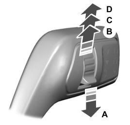
Ford Explorer 2020-2026 Owners Manual: Autowipers (If Equipped)
Wet or winter driving conditions with ice, snow or salty road mist can cause inconsistent and unexpected wiping or smearing. A - High sensitivity. B - Autowipers On. C - Low sensitivity. Use the rotary control to adjust the sensitivity of the autowipers...
Categories
- Manuals Home
- 6th Generation Explorer Owners Manual
- 6th Generation Explorer Service Manual
- General Procedures - Rear Camber Adjustment
- Body and Paint
- Removal and Installation - Front Halfshaft Speed Sensor
- New on site
- Most important about car
Windshield Wipers
 Push the lever up or down to operate
the windshield wipers.
Push the lever up or down to operate
the windshield wipers.
A - Single wipe.