Ford Explorer: Voltage Converter/Inverter / Removal and Installation - Direct Current/Direct Current (DC/DC) Converter Control Module
Removal
.jpg) WARNING:
Disconnect the 12 volt battery before servicing the direct
current to alternating current (DC-AC) inverter or alternating current
(AC) powerpoint to prevent the risk of high voltage shock. Failure to
follow this instruction may result in serious personal injury.
WARNING:
Disconnect the 12 volt battery before servicing the direct
current to alternating current (DC-AC) inverter or alternating current
(AC) powerpoint to prevent the risk of high voltage shock. Failure to
follow this instruction may result in serious personal injury.
-
NOTE: If installing a new module, it is necessary to upload the module configuration information to the scan tool prior to removing the module. This information must be downloaded into the new module after installation.
Upload the Direct Current/Direct Current (DC/DC) configuration to the scan tool by following the scan tool on-screen instructions.
-
Disconnect the battery negative terminal.
Refer to: Battery Disconnect and Connect (414-01 Battery, Mounting and Cables, General Procedures).
-
De-energize the high voltage system.
Refer to: High Voltage System De-energizing (414-03 High Voltage Battery, Mounting and Cables, General Procedures).
-
Remove the PCM.
Refer to: Powertrain Control Module (PCM) (303-14C Electronic Engine Controls - 3.3L Duratec-V6/3.3L Duratec-V6 – Hybrid (BP), Removal and Installation).
-
Remove the front RH headlamp assembly.
Refer to: Headlamp Assembly (417-01 Exterior Lighting, Removal and Installation).
-
Detach the wiring harness retainers and position aside the harness.
.jpg) |
-
Detach the wiring harness retainers and position aside the harness.
.jpg) |
-
Remove the bolts and the PCM bracket.
Torque: 53 lb.in (6 Nm)
.jpg) |
-
Disconnect the Direct Current/Direct Current (DC/DC) converter control module electrical connectors.
.jpg) |
-
Remove the coolant hoses.
.jpg) |
-
Position aside the battery terminal cover.
.jpg) |
-
Disconnect the battery positive terminal.
Torque: 159 lb.in (18 Nm)
.jpg) |
-
-
Remove the retainers.
Torque: 53 lb.in (6 Nm)
-
Remove the retainers.
Torque: 159 lb.in (18 Nm)
-
Remove the retainers.
.jpg) |
-
Disconnect the horn electrical connector.
.jpg) |
-
Remove the bolt and the horn assembly.
Torque: 26 lb.ft (35 Nm)
.jpg) |
-
NOTE: Lower right-hand side DC/DC converter control module to bracket fastener accessed through horn slot.
Remove the fasteners and the DC/DC converter control module.
Torque: 53 lb.in (6 Nm)
.jpg) |
Installation
-
To install, reverse the removal procedure.
-
If replacing the module, download the Direct
Current/Direct Current (DC/DC) converter control module configuration
information from the scan tool to the new Direct Current/Direct Current
(DC/DC) converter control module following the scan tool on-screen
instructions.
-
Bleed the cooling system.
Refer to: Cooling System Filling and Bleeding (303-03E Electric Powertrain Cooling - 3.3L Duratec-V6 – Hybrid (BP), General Procedures).
 Removal and Installation - Direct Current/Alternating Current (DC/AC) Inverter
Removal
WARNING:
Disconnect the 12 volt battery before servicing the direct
current to alternating current (DC-AC) inverter or alternating current
(AC) powerpoint to prevent the risk of ..
Other information:
Ford Explorer 2020-2026 Service Manual: Removal and Installation - Battery Cables - 2.3L EcoBoost (201kW/273PS)
Removal NOTE: This procedure provides information about routing, retaining points and connectors of the cable. It does not include the steps for removing components to gain access to the cable. Disconnect the battery. Refer to: Battery Disconnect and Connect (414-01 Battery, Mounting and Cables, General Procedures)...
Ford Explorer 2020-2026 Service Manual: Diagnosis and Testing - Body Control Module C (BCMC)
Diagnostic Trouble Code (DTC) Chart Diagnostics in this manual assume a certain skill level and knowledge of Ford-specific diagnostic practices. REFER to: Diagnostic Methods (100-00 General Information, Description and Operation). Diagnostic Trouble Code Chart Module DTC Description Action BCMC U0100:..
Categories
- Manuals Home
- 6th Generation Explorer Owners Manual
- 6th Generation Explorer Service Manual
- Engine
- Interior Trim and Ornamentation
- Auxiliary Power Points
- New on site
- Most important about car
Locking and Unlocking
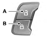
You can use the power door lock control or the remote control to lock and unlock your vehicle.
Power Door Locks
The power door lock control is on the driver and front passenger door panels.


