Ford Explorer: Electrical / Battery and Charging System
Ford Explorer 2020-2026 Service Manual / Electrical / Battery and Charging System
 Description and Operation - High Voltage Battery, Mounting and Cables - System Operation and Component Description
System Diagram
Item
Description
1
Current Sensor
2
Contactor Sense Leads
3
BECM
4
Precharge Contactor Coil
5
Positive Contactor Coil
6
Negative ..

Other information:
Ford Explorer 2020-2026 Service Manual: Removal and Installation - Rear Side Marker Flashing Light Emitting Diode (LED) Lamps
Special Tool(s) / General Equipment Interior Trim Remover Removal NOTE: Removal steps in this procedure may contain installation details. NOTE: LH lamp assembly shown, RH lamp assembly is similar. Remove the loadspace trim panel...
Ford Explorer 2020-2026 Service Manual: Removal and Installation - Rear Stabilizer Bar
Removal NOTICE: Suspension fasteners are critical parts that affect the performance of vital components and systems. Failure of these fasteners may result in major service expense. Use the same or equivalent parts if replacement is necessary. Do not use a replacement part of lesser quality or substitute design...
Categories
- Manuals Home
- 6th Generation Explorer Owners Manual
- 6th Generation Explorer Service Manual
- Fuel Filler Funnel Location & Running Out of Fuel
- Body and Paint
- Automatic Transmission
- New on site
- Most important about car
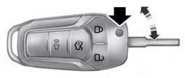
Integrated Keyhead Transmitter (If Equipped)
Use the key blade to start your vehicle and unlock or lock the driver door from outside your vehicle. The integrated keyhead transmitter functions as a programmed ignition key that operates all the locks and starts your vehicle, as well as a remote control.
Copyright © 2026 www.foexplorer.com