Ford Explorer: High Voltage Battery, Mounting and Cables / Description and Operation - High Voltage Battery, Mounting and Cables - System Operation and Component Description
System Diagram
.jpg)
.jpg)
| Item | Description |
|---|---|
| 1 | Current Sensor |
| 2 | Contactor Sense Leads |
| 3 | BECM |
| 4 | Precharge Contactor Coil |
| 5 | Positive Contactor Coil |
| 6 | Negative Contactor Coil |
| 7 | High Voltage Battery Junction Box |
| 8 | Temperature Sensors |
| 9 | Cell Voltage Sense Leads |
| 10 | PCM |
| 11 | Battery Cell Arrays |
| 12 | GWM |
| 13 | RCM |
| 14 | DCDC |
| 15 | 12 VoltBMS |
| 16 | TCU |
| 17 | Ignition Switch |
| 18 | Main 12 Volt Battery |
| 19 | HVAC |
| 20 | Service Disconnect |
| 21 | High Voltage Battery Coolant Diverter Valve |
| 22 | Motor Electronics Coolant Pump |
| 23 | Isolation Switch (BIB) |
| 24 | Auxiliary 12 Volt Battery |
| 25 | Coolant Temperature Sensor |
| 26 | High Voltage Battery |
| 27 | BCM |
| 28 | High Voltage Battery Coolant Pump |
| 29 | BCMC |
| 30 | SOBDMC |
| 31 | High Voltage Interlock Loop (HVIL) |
System Operation
Network Message Chart - Battery Energy Control Module (BECM)
| Broadcast Message | Originating Module | Message Purpose |
| 12V battery voltage | BCM | Battery voltage measured with battery sensor. |
| Accelerator pedal position | PCM | Accelerator pedal position used for OBDII freeze frame data. |
| Engine coolant temperature | PCM | Engine coolant temperature used for OBDII freeze frame data. |
| Engine load | PCM | Engine calculated load value used for OBDII freeze frame data. |
| Engine RPM | PCM | Engine RPM used for OBDII freeze frame data. |
| Engine warm-up completion status | PCM | Used to increment counters for DTC aging. |
| High voltage battery estimated current flow | SOBDMC | Estimated electric current into or out of the high voltage battery. |
| High voltage battery contactor request | PCM | Command to high voltage battery controller to open, close, or retain the high voltage contactor position. |
| High voltage battery contactor supply voltage status | SOBDMC | Used to determine if the 12V contactor supply voltage is asserted or not asserted. |
| High voltage battery coolant flow request during high voltage battery coolant cooler operation | SOBDMC | Coolant flow request to support cooling of the high voltage batery during high voltage batttery coolant cooler operation. |
| SOBDMC coolant flow request | SOBDMC | Coolant flow request to support cooling of the SOBDMC. |
| High voltage interlock circuit open status | SOBDMC | Notifies the BECM if a high voltage interlock circuit is open which disables the high voltage system. |
| Hybrid DC/DC high voltage measurement | DCDC | Voltage of the high voltage bus as seen by the DCDC. |
| Hybrid DC/DC low voltage measurement | DCDC | Voltage of the low voltage bus as seen by the DCDC. |
| Hybrid DC/DC coolant flow request | DCDC | Coolant flow request to support cooling of the DCDC. |
| Hybrid transaxle inverter voltage | SOBDMC | Voltage on the high voltage cable at the input to the hybrid transaxle. |
| Ignition status | BCM | Current ignition state; off, accessory, run, start, unknown or invalid. |
| Power pack torque status | PCM | Power pack is on or off and if torque is available. |
| Restraint impact event status (gateway) | RCM | Used to disable the high voltage system during a crash. |
| Transmission selector (PRNDL) status | PCM | Used to determine transaxle gear state. |
| Vehicle speed | PCM | Vehicle speed data. |
| Odometer master value (gateway) | IPC | Vehicle odometer value. |
| Vehicle configuration data | BCM | Vehicle configuration strategy. |
Cell Balancing
Individual cells can deviate over the life of the high voltage battery. The purpose of cell balancing is to equalize the individual cell charges. By balancing the cells the high voltage battery maintains top efficiency. The BECM continuously monitors individual battery cell voltages and will perform balancing when required and when certain conditions are met.
Vehicle Shut Down
A vehicle shut down signal is sent by the BECM when the BECM is about to open the contactors due to an internal fault or has just opened the contactors due to an external input (external module commanding contactors to be opened such as a crash event or interlock circuit failure). When vehicle shut down occurs, the Stop Safely warning indicator is illuminated warning that the vehicle will be shut down within a matter of seconds and the operator should pull off the road as soon as possible. Depending on the fault condition that lead to the shutdown, the vehicle may or may not restart if the condition has corrected itself. If the fault condition is severe enough, the fault will have to be repaired and Diagnostic Trouble Codes (DTCs) cleared before the vehicle will restart.
Component Description
High Voltage Battery
The high voltage battery consists of pouch cells packaged into modules which deliver approximately 300 volts DC to the high voltage system. The high voltage battery supplies electrical energy to the electric motor to move the vehicle when it is operating in electric mode only or to assist the gasoline engine (heavy acceleration). When the engine is operating or the vehicle is moving, the electric motor can be used as a generator creating high-voltage AC electricity. High-voltage AC generated by the electric motor is converted to high voltage DC by the SOBDMC and transmitted through the high voltage cables to recharge the high voltage battery.
The high-voltage DC electrical power is converted to low voltage DC electrical power through the Direct Current/Direct Current (DC/DC) converter control module. This low-voltage high current DC electrical power is then supplied to the 12-volt batteries through the low voltage battery cables.
The high-voltage system has a floating ground. The floating ground is designed to completely isolate the high-voltage system from the vehicle chassis. The high-voltage cables are fully insulated (isolated) from all vehicle components and circuits. There are no common connections (such as body grounds) used to conduct the high-voltage power. The BECM monitors this system for any leakage of current to the normal electrical system (similar to a household ground fault interrupter). There are high voltage circuits from the battery cell arrays to the BECM used to monitor isolation resistance between the high voltage battery and chassis.
Battery Energy Control Module (BECM)
The BECM manages the condition of the high voltage battery to control its charging and discharging. The BECM controls the high voltage battery coolant pump in conjunction with BCMC controlling the diverter valve. When additional high voltage battery cooling is needed (high ambient temperatures and/or during high current flow demand) the coolant diverter valve is energized to allow coolant to be diverted through the high voltage battery chiller. The high voltage battery chiller is part of the HVAC system used to chill the coolant prior to being returned to the high voltage battery.
The BECM monitors the individual cell voltages and temperature sensors internal to the battery arrays. The BECM monitors the battery current using a sensor located in the high voltage battery junction box. This information is needed by the BECM to control the high voltage battery and determine its ability to receive and provide power to the vehicle. The BECM communicates with other vehicle modules on the HS-CAN.
The BECM receives the following hard-wired inputs:
- HEV (Hybrid Electric Vehicle) wakeup
- High voltage battery connector interlock status
- High voltage battery contactor control supply voltage (includes the service disconnect)
- High voltage battery cells sense leads
- High voltage battery cell temperature sensors
- High voltage battery coolant inlet temperature sensor
- High voltage battery coolant pump feedback signal
- Motor electronics coolant pump feedback signal
- Current sensor (part of the high voltage battery junction box)
- Event notification status from the RCM
- HS-CAN
The BECM provides the following outputs:
- High voltage battery coolant pump PWM control signal
- Motor eletronics coolant pump PWM control signal
- High voltage battery junction box pre-charge contactor control
- High voltage battery junction box positive contactor control
- High voltage battery junction box negative contactor control
- HS-CAN information
Direct Current/Direct Current (DC/DC) Converter Control Module
The DCDC is an liquid-cooled component that converts high voltage DC power to low-voltage (12-volt) DC power. The converter provides power to the vehicle 12-volt battery and low-voltage electrical systems. The PCM requests the DCDC to enable power conversion through an enable message over HS-CAN. The PCM sends a charging voltage setpoint request over HS-CAN to the DCDC. For information on the DCDC,
Refer to: Direct Current/Direct Current (DC/DC) Converter Control Module - System Operation and Component Description (414-05 Voltage Converter/Inverter, Description and Operation).
Hybrid Electric Motor Assembly
The hybrid electric motor assembly is mounted to the front of the transmission assembly and is also used as an generator. The assembly also incorporates an electric operated engine disconnect clutch that engages or disengages the electric motor from the gasoline engine.
The electric motor generates high voltage electricity for charging the high voltage battery. The engine is started using either conventional engine block mounted starter (for cold starts only) and a Belt Integrated Starter Generator (BISG) for other starts during normal vehicle operation. The electric motor must be energized and rotated to match gasoline engine cranking speed during starting. If the high voltage system is shutdown due to a malfunction the gasoline engine will not start and the vehicle will be disabled.
The
electric motor is used to accelerate the vehicle from a stop when
driving under electric power. The electric motor is also used to recover
energy during regenerative braking. The electric motor receives power
from the high voltage battery after the high voltage battery junction
box contactors have closed. For information on the electric motor and
its operation,
Refer to: Electric Motor (303-01E Electric Motor, Description and Operation).
During
braking and deceleration events the regenerative brake system utilizes
the electric motor as a generator to create and capture electrical
current. This captured energy is used to charge the high voltage
battery. If the high voltage battery is adequately charged, the captured
energy is used for gas engine braking to slow the vehicle. The
regenerative brake system is a series system which the generator braking
is used first, up to the limits of the generator torque capacity and
the high voltage battery charging capacity. After optimum regeneration
is used, the friction brakes are applied to supplement braking demands.
For information on regenerative braking,
Refer to: Anti-Lock Brake System (ABS) and Stability Control - System Operation and Component Description (206-09 Anti-Lock Brake System (ABS) and Stability Control, Description and Operation).
High Voltage Battery Junction Box
The high voltage battery junction box acts as an interface between the high-voltage cable assembly and the high voltage battery. The high voltage battery junction box houses the 3 contactors (precharge, positive and negative) which, when commanded closed by the BECM, connect the high voltage battery to various components for high-voltage consumption and/or charging of the high voltage battery. During initial power up the precharge contactor closes prior to the positive contactor which routes high voltage through the precharge resistor which is also located in the high voltage battery junction box. This reduces the in rush current to the capacitors and prevents contactor arcing. The high voltage battery junction box design enables distribution of high-voltage to the high current side SOBDMC and the low current side (Direct Current/Direct Current (DC/DC) converter control module and the ACCM. The high current side for the SOBDMC is protected by a high-voltage high current 150A fuse. The low current side for the Direct Current/Direct Current (DC/DC) converter control module and ACCM are protected by a high-voltage low current 50A fuse. Any fault resulting in excessive current on the low current side will open the fuse and stop power conversion at the Direct Current/Direct Current (DC/DC) and ACCM. The excessive current will not transfer onto the high-current side. The high voltage battery junction box contains the contactors, the current sensor, high voltage interlock circuit, high-voltage high current 150A fuse, and a high-voltage low current 50A fuse.
The high voltage battery junction box contains a current sensor that is hardwired to and monitored by the BECM. The current sensor helps determine the load or rate of charge of the high voltage battery by sensing current flow into or out of the high voltage battery. The high voltage battery junction box also contains voltage sense points downstream of the high voltage contactors that are used to detect issues with the contactors.
High Voltage Cable Assembly
All cables that carry high voltage are integrated into one high-voltage cable assembly that connects the High Voltage Battery, SOBDMC, DCDC, and the ACCM. There are 4 circuits that connect to the High Voltage Battery. Two main circuits supply high voltage to the SOBDMC. Two auxillary circuits supply high voltage to the DCDC. The DCDC acts as a junction and sends high voltage to the ACCM. There is a seperate 3 phase AC high voltage cable assembly that connects the Hybrid Electric Motor Assembly and the SOBDMC.
High Voltage System Service Disconnect Plug
The
high voltage system uses a low voltage disconnect plug that opens the
12-Volt contactor control supply circuit and is located in the engine
compartment. When the service disconnect plug is disconnected the high
voltage battery contactors that supply high voltage to the vehicle are
unable to close. The high voltage system must be depowered prior to
disconnecting any high voltage cable (identified by orange color).
Refer to: High Voltage System De-energizing (414-03 High Voltage Battery, Mounting and Cables, General Procedures).
 Description and Operation - High Voltage Battery, Mounting and Cables - Overview
OVERVIEW
WARNING:
To prevent the risk of high-voltage shock, always follow
precisely all warnings and service instructions, including instructions
to depower the system...

Other information:
Ford Explorer 2020-2025 Service Manual: Removal and Installation - Brake Disc
Materials Name Specification Motorcraft® Metal Brake Parts CleanerPM-4-A, PM-4-B - Removal WARNING: Service actions on vehicles equipped with electronic brake booster and electronic parking brakes may cause unexpected brake application, which could result in injury to hands or fingers...
Ford Explorer 2020-2025 Service Manual: Specifications
General Specifications Item Specification 2.3L EcoBoost - Limited and XLT with trailer tow vehicles built before October 2020 Rating 220 amps Generator amps at 80.6°F (27°C) 117...
Categories
- Manuals Home
- 6th Generation Explorer Owners Manual
- 6th Generation Explorer Service Manual
- Body and Paint
- Traction Control
- Description and Operation - Identification Codes
- New on site
- Most important about car
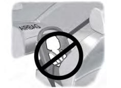
Children and Airbags
WARNING: Airbags can kill or injure a child in a child restraint. Never place a rear-facing child restraint in front of an active airbag. If you must use a forward-facing child restraint in the front seat, move the seat upon which the child restraint is installed all the way back.