Ford Explorer: Electronic Engine Controls - 2.3L EcoBoost (201kW/273PS) / Removal and Installation - Cylinder Head Temperature 2 (CHT2) Sensor
Ford Explorer 2020-2026 Service Manual / Powertrain / Engine / Electronic Engine Controls - 2.3L EcoBoost (201kW/273PS) / Removal and Installation - Cylinder Head Temperature 2 (CHT2) Sensor
Materials
| Name | Specification |
|---|---|
| Motorcraft® Silicone Brake Caliper Grease and Dielectric Compound XG-3-A |
ESE-M1C171-A |
Removal
-
NOTICE: Do not pull the engine appearance cover forward or sideways to remove. Failure to press straight upward on the underside of the cover at the attachment points may result in damage to the cover or engine components.
-
Remove the engine appearance cover nut.
-
Place your hand under the engine appearance cover at
each grommet location and pull straight up to release each grommet from
the studs.
-
After all of the grommets have been released from the studs, remove the appearance cover from the engine.
-
Remove the engine appearance cover nut.
.jpg) |
-
Position aside the CHT 2 (CHT2) sensor cover. Disconnect the electrical connector.
.jpg) |
-
-
Remove the cylinder head temperature 2 (CHT2) sensor and heat shield.
Torque: 97 lb.in (11 Nm)
-
Remove the cylinder head temperature 2 (CHT2) sensor and heat shield.
.jpg) |
Installation
-
To install, reverse the removal procedure.
-
-
NOTE: Lubricating the grommets with silicone grease will aid in the installation of the engine appearance cover, and any future removal and installation of the cover.
Lubricate each grommet with silicone grease.
Material: Motorcraft® Silicone Brake Caliper Grease and Dielectric Compound / XG-3-A (ESE-M1C171-A)
-
Position the engine appearance cover onto engine with the grommets aligned with the studs.
-
Press down on the engine appearance cover at each grommet location to attach the grommets onto the studs.
-
Install the engine appearance cover nut.
Torque: 44 lb.in (5 Nm)
-
If the engine appearance cover stud bolt is loosened
or removed, it must be installed/tightened into the valve cover.
Torque: 62 lb.in (7 Nm)
-
|
 Removal and Installation - Crankshaft Position (CKP) Sensor
Special Tool(s) /
General Equipment
303-1521Alignment Tool, Crankshaft Position SensorTKIT-2010C-FLM
303-507Timing Peg, Crankshaft TDCTKIT-2001N-FLMTKIT-2001N-ROW
Removal
NOTICE..
 Removal and Installation - Engine Coolant Temperature (ECT) Sensor
Removal
NOTE:
Removal steps in this procedure may contain installation details.
Remove the EGR cooler.
Refer to: Exhaust Gas Recirculation (EGR) Cooler (303-08A Engine Emission Control ..
Other information:
Ford Explorer 2020-2026 Service Manual: Description and Operation - Blind Spot Information System - System Operation and Component Description
System Operation BLIS® and CTA System Diagram Item Description 1 GWM 2 SCCM 3 HS-CAN1 4 HS-CAN2 5 HS-CAN3 6 IPC 7 PCM 8 DDM 9 PDM 10 MS-CAN 11 BCM 12 PAM 13 ACM 14 HS-CAN3 15 LH exterior mirror 16 LH BLIS®/ CTA L..
Ford Explorer 2020-2026 Service Manual: Removal and Installation - Thermostatic Expansion Valve - 2.3L EcoBoost (201kW/273PS)
Removal NOTICE: During the removal of components, cap, tape or otherwise appropriately protect all openings to prevent the ingress of dirt or other contamination. Remove protective materials prior to installation. NOTE: Removal steps in this procedure may contain installation details...
Categories
- Manuals Home
- 6th Generation Explorer Owners Manual
- 6th Generation Explorer Service Manual
- Driveline
- Electric Parking Brake
- Engine
- New on site
- Most important about car
Windshield Wipers
 Push the lever up or down to operate
the windshield wipers.
Push the lever up or down to operate
the windshield wipers.
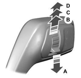
A - Single wipe.
Copyright © 2026 www.foexplorer.com