
Ford Explorer: Electronic Feature Group / Multifunction Electronic Modules
Ford Explorer 2020-2026 Service Manual / Electrical / Electronic Feature Group / Multifunction Electronic Modules
- Description and Operation - Module Controlled Functions - Component Location
- Description and Operation - Module Controlled Functions - Overview
- Description and Operation - Module Controlled Functions - System Operation and Component Description
- Diagnosis and Testing - Body Control Module (BCM)
- Diagnosis and Testing - Body Control Module C (BCMC)
- General Procedures - Factory Mode Deactivation
- General Procedures - Transport Mode Deactivation
- Removal and Installation - Body Control Module (BCM)
- Removal and Installation - Body Control Module C (BCMC)
- Removal and Installation - Driver Door Module (DDM)
- Removal and Installation - Passenger Door Module (PDM)
- Removal and Installation - Radio Transceiver Module (RTM)
 Removal and Installation - Image Processing Module A (IPMA)
Removal
Release the clips and remove the IPMA cover.
Disconnect the electrical connector.
Release the tabs and remove the IPM..

Other information:
Ford Explorer 2020-2026 Service Manual: Removal and Installation - Output Shaft Seal
Special Tool(s) / General Equipment 100-001 (T50T-100-A) Slide Hammer 205-1018Installation Tube 307-309Remover, Torque Converter SealTKIT-1994-FMH/FLMHTKIT-1994-LMH/MHTKIT-1994-FH 307-782Installer, Output Shaft Seal Punch Removal With the vehicle in NEUTRAL, position it on a hoist...
Ford Explorer 2020-2026 Owners Manual: Automatic Transmission
WARNING: Always fully apply the parking brake and make sure you shift into park (P). Failure to follow this instruction could result in personal injury or death. WARNING: Do not apply the brake pedal and accelerator pedal simultaneously. Applying both pedals simultaneously for more than a few seconds will limit engine performance, which may result in difficulty maintaining speed in traffi..
Categories
- Manuals Home
- 6th Generation Explorer Owners Manual
- 6th Generation Explorer Service Manual
- Fuel Filler Funnel Location & Running Out of Fuel
- Auxiliary Power Points
- Description and Operation - Identification Codes
- New on site
- Most important about car
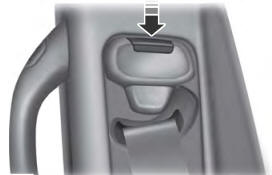
Seatbelt Height Adjustment
WARNING: Position the seatbelt height adjuster so that the seatbelt rests across the middle of your shoulder. Failure to adjust the seatbelt correctly could reduce its effectiveness and increase the risk of injury in a crash.

Copyright © 2026 www.foexplorer.com