Ford Explorer: Information and Entertainment System - General Information - Vehicles Without: SYNC 3 / Diagnosis and Testing - Information and Entertainment System - Vehicles Without: SYNC 3
Diagnostic Trouble Code (DTC) Chart
Diagnostics in this manual assume a certain skill level and knowledge of Ford-specific diagnostic practices.
REFER to: Diagnostic Methods (100-00 General Information, Description and Operation).
Diagnostic Trouble Code Chart
| Module | DTC | Description | Action |
|---|---|---|---|
| ACM | B108E:11 | Display:Circuit Short To Ground | GO to Pinpoint Test I |
| ACM | B108E:15 | Display:Circuit Short To Battery or Open | GO to Pinpoint Test I |
| ACM | B116A:11 | Handset Microphone:Circuit Short To Ground | GO to Pinpoint Test J |
| ACM | B116A:12 | Handset Microphone:Circuit Short To Battery | GO to Pinpoint Test J |
| ACM | B116A:14 | Handset Microphone:Circuit Short To Ground or Open | GO to Pinpoint Test J |
| ACM | B119F:11 | GPS Antenna:Short To Ground | GO to Pinpoint Test M |
| ACM | B119F:15 | GPS Antenna:Circuit Short To Battery or Open | GO to Pinpoint Test M |
| ACM | B1252:11 | USB Port:Circuit Short to Ground | GO to Pinpoint Test K |
| ACM | B1A01:01 | Speaker #1:General Electrical Failure | GO to Pinpoint Test F |
| ACM | B1A01:11 | Speaker #1:Circuit Short To Ground | GO to Pinpoint Test F |
| ACM | B1A01:12 | Speaker #1:Circuit Short To Battery | GO to Pinpoint Test F |
| ACM | B1A01:13 | Speaker #1:Circuit Open | GO to Pinpoint Test F |
| ACM | B1A02:01 | Speaker #2:General Electrical Failure | GO to Pinpoint Test F |
| ACM | B1A02:11 | Speaker #2:Circuit Short To Ground | GO to Pinpoint Test F |
| ACM | B1A02:12 | Speaker #2:Circuit Short To Battery | GO to Pinpoint Test F |
| ACM | B1A02:13 | Speaker #2:Circuit Open | GO to Pinpoint Test F |
| ACM | B1A03:01 | Speaker #3:General Electrical Failure | GO to Pinpoint Test F |
| ACM | B1A03:11 | Speaker #3:Circuit Short To Ground | GO to Pinpoint Test F |
| ACM | B1A03:12 | Speaker #3:Circuit Short To Battery | GO to Pinpoint Test F |
| ACM | B1A03:13 | Speaker #3:Circuit Open | GO to Pinpoint Test F |
| ACM | B1A04:01 | Speaker #4:General Electrical Failure | GO to Pinpoint Test F |
| ACM | B1A04:11 | Speaker #4:Circuit Short To Ground | GO to Pinpoint Test F |
| ACM | B1A04:12 | Speaker #4:Circuit Short To Battery | GO to Pinpoint Test F |
| ACM | B1A04:13 | Speaker #4:Circuit Open | GO to Pinpoint Test F |
| ACM | B1A56:11 | Antenna:Circuit Short To Ground | GO to Pinpoint Test A |
| ACM | B1A56:15 | Antenna:Circuit Short To Battery or Open | GO to Pinpoint Test A |
| ACM | U0100:00 | Lost Communication with ECM/PCM "A":No Sub Type Information | GO to Pinpoint Test N |
| ACM | U0155:00 | Lost Communication With Instrument Panel Cluster (IPC) Control Module:No Sub Type Information | GO to Pinpoint Test O |
| ACM | U0255:00 | Lost Communication With Front Display Interface Module:No Sub Type Information | GO to Pinpoint Test I |
| ACM | U1A00:08 | Private Communication Network:Bus Signal / Message Failure | GO to Pinpoint Test G |
| ACM | U2013:01 | Switch Pack:General Electrical Failure | GO to Pinpoint Test G |
| ACM | U2013:16 | Switch Pack:Circuit Voltage Below Threshold | GO to Pinpoint Test G |
| ACM | U2013:17 | Switch Pack:Circuit Voltage Above Threshold | GO to Pinpoint Test G |
| ACM | U2013:63 | Switch Pack:Circuit / Component Protection Time-Out | GO to Pinpoint Test G |
| ACM | U2019:54 | Control Module Software #4:Missing Calibration | GO to Pinpoint Test R |
| ACM | U201A:54 | Control Module Main Calibration Data:Missing Calibration | GO to Pinpoint Test R |
| ACM | U201A:57 | Control Module Main Calibration Data:Invalid / Incompatible Software Component | GO to Pinpoint Test R |
| ACM | U201C:54 | Control Module Calibration Data #3:Missing Calibration | GO to Pinpoint Test R |
| ACM | U2024:55 | Control Module Cal-Config Data:Not Configured | GO to Pinpoint Test R |
| ACM | U2100:00 | Initial Configuration Not Complete:No Sub Type Information | GO to Pinpoint Test R |
| ACM | U2101:00 | Control Module Configuration Incompatible:No Sub Type Information | GO to Pinpoint Test R |
| ACM | U2101:56 | Control Module Configuration Incompatible:Invalid / Incompatible Configuration | GO to Pinpoint Test R |
| ACM | U3000:41 | Control Module:General Checksum Failure | GO to Pinpoint Test S |
| ACM | U3000:42 | Control Module:General Memory Failure | GO to Pinpoint Test S |
| ACM | U3000:96 | Control Module:Component Internal Failure | GO to Pinpoint Test S |
| ACM | U3003:16 | Battery Voltage:Circuit Voltage Below Threshold | GO to Pinpoint Test P |
| ACM | U3003:17 | Battery Voltage:Circuit Voltage Above Threshold | GO to Pinpoint Test Q |
| SCCM | B1380:11 | Steering Wheel Right Switch Pack:Circuit Short To Ground | GO to Pinpoint Test H |
| SCCM | B1380:13 | Steering Wheel Right Switch Pack:Circuit Open | GO to Pinpoint Test H |
| SCCM | B1380:96 | Steering Wheel Right Switch Pack:Component Internal Failure | GO to Pinpoint Test H |
| SCCM | B1380:9E | Steering Wheel Right Switch Pack:Stuck On | GO to Pinpoint Test H |
Symptom Charts
Symptom Chart: Radio
Diagnostics in this manual assume a certain skill level and knowledge of Ford-specific diagnostic practices.
REFER to: Diagnostic Methods (100-00 General Information, Description and Operation).
| Condition | Possible Sources | Actions |
|---|---|---|
| A module does not respond to the diagnostic scan tool | Refer to the Pinpoint Test |
REFER to: Communications Network (418-00 Module Communications Network, Diagnosis and Testing). |
| The AM radio is inoperative | Refer to the Pinpoint Test | GO to Pinpoint Test A |
| The FM radio is inoperative | Refer to the Pinpoint Test | GO to Pinpoint Test A |
| Poor AM reception | Refer to the Pinpoint Test | GO to Pinpoint Test A |
| Poor FM reception | Refer to the Pinpoint Test | GO to Pinpoint Test A |
| Continuous seek or scan in AM/ FM mode | Refer to the Pinpoint Test | GO to Pinpoint Test A |
| One or more audio steering wheel control button is inoperative | Refer to the Pinpoint Test | GO to Pinpoint Test H |
| The audio system does not operate correctly from the radio control panel | Refer to the Pinpoint Test | GO to Pinpoint Test G |
Symptom Chart: Speakers and Sound Quality
Diagnostics in this manual assume a certain skill level and knowledge of Ford-specific diagnostic practices.
REFER to: Diagnostic Methods (100-00 General Information, Description and Operation).
| Condition | Possible Sources | Actions |
|---|---|---|
| A loud popping sound is heard from the speakers when cycling the ignition on | Refer to the Pinpoint Test | GO to Pinpoint Test B |
| No sound from all speakers | Refer to the Pinpoint Test | GO to Pinpoint Test C |
| Poor sound quality or distorted sound from one or more speakers (not all speakers) | Refer to the Pinpoint Test | GO to Pinpoint Test D |
| The speed compensated volume does not operate correctly | Refer to the Pinpoint Test | GO to Pinpoint Test E |
| The left front door speaker is inoperative | Refer to the Pinpoint Test | GO to Pinpoint Test F |
| The right front door speaker is inoperative | Refer to the Pinpoint Test | GO to Pinpoint Test F |
| The left rear door speaker is inoperative | Refer to the Pinpoint Test | GO to Pinpoint Test F |
| The right rear door speaker is inoperative | Refer to the Pinpoint Test | GO to Pinpoint Test F |
Symptom Chart: Display Unit
Diagnostics in this manual assume a certain skill level and knowledge of Ford-specific diagnostic practices.
REFER to: Diagnostic Methods (100-00 General Information, Description and Operation).
| Condition | Possible Sources | Actions |
|---|---|---|
| The display unit is blank or black | Refer to the Pinpoint Test | GO to Pinpoint Test I |
| The display unit is not responsive to touch | Refer to the Pinpoint Test | GO to Pinpoint Test I |
| The display unit is slow to respond to touch | Refer to the Pinpoint Test | GO to Pinpoint Test I |
| The image displayed is incorrect, the image color is incorrect, or the image is distorted, flickering or unclear | Refer to the Pinpoint Test | GO to Pinpoint Test I |
| The image on the display unit is locked or frozen | Refer to the Pinpoint Test | GO to Pinpoint Test I |
Symptom Chart: Audio Unit Media/Phone Features
Diagnostics in this manual assume a certain skill level and knowledge of Ford-specific diagnostic practices.
REFER to: Diagnostic Methods (100-00 General Information, Description and Operation).
| Condition | Possible Sources | Actions |
|---|---|---|
| Outgoing audio is not transmitted during a phone call | Refer to the Pinpoint Test | GO to Pinpoint Test J |
| A USB device is not recognized by the audio system or audio files on a USB device are not found using the audio system from one or both USB ports | Refer to the Pinpoint Test | GO to Pinpoint Test K |
| An individual Bluetooth device or feature is inoperative | Device compatibility | GO to Pinpoint Test L |
| Unable to pair Bluetooth device or the Bluetooth functionality is inoperative | Refer to the Pinpoint Test | GO to Pinpoint Test L |
Symptom Chart: Compass
Diagnostics in this manual assume a certain skill level and knowledge of Ford-specific diagnostic practices.
REFER to: Diagnostic Methods (100-00 General Information, Description and Operation).
| Condition | Possible Sources | Actions |
|---|---|---|
| The compass is inoperative or does not operate correctly | Refer to the Pinpoint Test | GO to Pinpoint Test M |
Pinpoint Tests
|
Refer to Wiring Diagrams Cell 130 for schematic and connector information. Normal Operation and Fault Conditions
REFER to: Information and Entertainment System - Component Location (415-00A Information and Entertainment System - General Information - Vehicles Without: SYNC 3, Description and Operation). Antenna Cable Connections .jpg)
DTC Fault Trigger Conditions
Possible Sources
Visual Inspection and Pre-checks
|
||||||||||||||||||
| NOTE: Prior to carrying out diagnostics, it may be beneficial to determine the cause using the Antenna Kit Tool 420-525 (Rotunda part number NUD420-525) or equivalent tool. | ||||||||||||||||||
| A1 CHECK THE AUDIO SYSTEM RECEPTION WITH THE ENGINE RUNNING | ||||||||||||||||||
Does the poor reception only occur with the engine running?
|
||||||||||||||||||
| A2 CHECK THE AUDIO SYSTEM RECEPTION WITH THE ENGINE RUNNING AND THE REAR DEFROST FUNCTION DEACTIVATED | ||||||||||||||||||
Does the poor reception occur with the rear window defrost function deactivated?
|
||||||||||||||||||
| A3 CHECK THE GENERATOR | ||||||||||||||||||
Is the reception OK?
|
||||||||||||||||||
| A4 CHECK THE IGNITION CIRCUITS | ||||||||||||||||||
Are the ignition components OK?
|
||||||||||||||||||
| A5 INSPECT THE ANTENNA ON-GLASS GRID | ||||||||||||||||||
Is the connection to the antenna amplifier OK and the on-glass antenna grid free from damage?
|
||||||||||||||||||
| A6 CHECK FOR ACM (AUDIO FRONT CONTROL MODULE) ANTENNA CABLE VOLTAGE OUTPUT | ||||||||||||||||||
Is the voltage greater than 10 volts?
|
||||||||||||||||||
| A7 CHECK FOR VOLTAGE TO THE ANTENNA AMPLIFIER | ||||||||||||||||||
Is the voltage greater than 10 volts?
|
||||||||||||||||||
| A8 ISOLATE THE AM (AMPLITUDE MODULATION) / FM (FREQUENCY MODULATION) 1 ANTENNA AMPLIFIER | ||||||||||||||||||
Is the reception OK?
|
||||||||||||||||||
| A9 CHECK FOR CORRECT ACM (AUDIO FRONT CONTROL MODULE) OPERATION | ||||||||||||||||||
Is the concern still present?
|
.jpg)
.jpg) AM/ FM1 antenna cable core at the AM/ FM1 antenna amplifier
AM/ FM1 antenna cable core at the AM/ FM1 antenna amplifier
.jpg)
|
Refer to Wiring Diagrams Cell 130 for schematic and connector information. Normal Operation and Fault Conditions
REFER to: Information and Entertainment System - System Operation and Component Description (415-00A Information and Entertainment System - General Information - Vehicles Without: SYNC 3, Description and Operation). Possible Sources
|
||||
| B1 CHECK FOR BCM (BODY CONTROL MODULE) DIAGNOSTIC TROUBLE CODES (DTCS) | ||||
Are any Diagnostic Trouble Codes (DTCs) present?
|
||||
| B2 CHECK FOR ACM (AUDIO FRONT CONTROL MODULE) DIAGNOSTIC TROUBLE CODES (DTCS) | ||||
Are any Diagnostic Trouble Codes (DTCs) present?
|
||||
| B3 CHECK FOR CORRECT ACM (AUDIO FRONT CONTROL MODULE) OPERATION | ||||
Is the concern still present?
|
|
Refer to Wiring Diagrams Cell 130 for schematic and connector information. Normal Operation and Fault Conditions
REFER to: Information and Entertainment System - System Operation and Component Description (415-00A Information and Entertainment System - General Information - Vehicles Without: SYNC 3, Description and Operation). A short to ground or voltage in the circuitry to one of the speakers may cause multiple speakers to lose sound due to the built-in overload protection feature of the ACM. In this case, a speaker fault DTC sets. Possible Sources
|
||||
| C1 VERIFY THE ACM (AUDIO FRONT CONTROL MODULE) PASSES THE NETWORK TEST | ||||
Does the ACM pass the network test?
|
||||
| C2 CHECK FOR ACM (AUDIO FRONT CONTROL MODULE) DIAGNOSTIC TROUBLE CODES (DTCS) | ||||
Are any Diagnostic Trouble Codes (DTCs) present?
|
||||
| C3 CHECK FOR CORRECT ACM (AUDIO FRONT CONTROL MODULE) OPERATION | ||||
Is the concern still present?
|
|
Normal Operation and Fault Conditions
REFER to: Information and Entertainment System - Overview (415-00A Information and Entertainment System - General Information - Vehicles Without: SYNC 3, Description and Operation). Possible Sources
Visual Inspection and Pre-checks
|
||||
| D1 ISOLATE THE ZONE | ||||
Does applying pressure to a trim panel reduce or eliminate the noise?
|
||||
| D2 REMOVE AND INSPECT BEHIND/UNDERNEATH THE SUSPECT TRIM PANEL | ||||
Is the source of the noise located?
|
||||
| D3 CHECK THE SUSPECT SPEAKER FOR WATER INTRUSION | ||||
Are any watermarks present on the speaker?
|
||||
| D4 ISOLATE THE SUSPECT SPEAKER TO VERIFY NOISE | ||||
Is the noise still present in the suspect speaker?
|
|
Normal Operation and Fault Conditions
REFER to: Information and Entertainment System - Overview (415-00A Information and Entertainment System - General Information - Vehicles Without: SYNC 3, Description and Operation). Possible Sources
|
||||
| E1 CHECK THE SPEEDOMETER OPERATION | ||||
Does the speedometer operate correctly?
|
||||
| E2 CHECK THE SPEED COMPENSATED VOLUME SETTING | ||||
|
NOTE: Refer to the Owner Literature to access the speed compensated volume settings.
Does the volume remain constant with the speed compensated volume turned off, and increase and decrease with vehicle speed with the speed compensated volume set to maximum?
|
||||
| E3 CHECK FOR ACM (AUDIO FRONT CONTROL MODULE) DIAGNOSTIC TROUBLE CODES (DTCS) | ||||
Are any Diagnostic Trouble Codes (DTCs) present?
|
||||
| E4 CHECK FOR CORRECT ACM (AUDIO FRONT CONTROL MODULE) OPERATION | ||||
Is the concern still present?
|
|
Refer to Wiring Diagrams Cell 130 for schematic and connector information. Normal Operation and Fault Conditions
REFER to: Information and Entertainment System - Overview (415-00A Information and Entertainment System - General Information - Vehicles Without: SYNC 3, Description and Operation). DTC Fault Trigger Conditions
Possible Sources
|
|||||||||||||||||||||||||||||||||||||||||||||||||||
| F1 CHECK THE AUDIO CIRCUITS TO THE SPEAKER FOR A SHORT TO GROUND | |||||||||||||||||||||||||||||||||||||||||||||||||||
Are the resistances greater than 10,000 ohms?
|
|||||||||||||||||||||||||||||||||||||||||||||||||||
| F2 CHECK THE AUDIO CIRCUITS TO THE SPEAKER FOR A SHORT TO VOLTAGE | |||||||||||||||||||||||||||||||||||||||||||||||||||
Is any voltage present?
|
|||||||||||||||||||||||||||||||||||||||||||||||||||
| F3 CHECK THE AUDIO CIRCUITS TO THE SPEAKER FOR A SHORT TOGETHER | |||||||||||||||||||||||||||||||||||||||||||||||||||
Are the resistances greater than 10,000 ohms?
|
|||||||||||||||||||||||||||||||||||||||||||||||||||
| F4 CHECK THE AUDIO CIRCUITS TO THE SPEAKER FOR AN OPEN | |||||||||||||||||||||||||||||||||||||||||||||||||||
Are the resistances less than 3 ohms?
|
|||||||||||||||||||||||||||||||||||||||||||||||||||
| F5 CHECK THE AUDIO SIGNAL TO THE SUSPECT SPEAKER | |||||||||||||||||||||||||||||||||||||||||||||||||||
Is a fluctuating AC voltage present?
|
|||||||||||||||||||||||||||||||||||||||||||||||||||
| F6 CHECK FOR CORRECT ACM (AUDIO FRONT CONTROL MODULE) OPERATION | |||||||||||||||||||||||||||||||||||||||||||||||||||
Is the concern still present?
|
.jpg)
|
Refer to Wiring Diagrams Cell 130 for schematic and connector information. Normal Operation and Fault Conditions
REFER to: Information and Entertainment System - System Operation and Component Description (415-00A Information and Entertainment System - General Information - Vehicles Without: SYNC 3, Description and Operation). DTC Fault Trigger Conditions
Possible Sources
Visual Inspection and Pre-checks
|
||||||||||||||||||
| G1 CHECK FOR VOLTAGE TO THE RADIO CONTROL PANEL | ||||||||||||||||||
Is the voltage greater than 11 volts?
|
||||||||||||||||||
| G2 CHECK THE RADIO CONTROL PANEL POWER SUPPLY CIRCUIT FOR AN OPEN | ||||||||||||||||||
Is the resistance less than 3 ohms?
|
||||||||||||||||||
| G3 CHECK THE RADIO CONTROL PANEL GROUND CIRCUIT FOR AN OPEN | ||||||||||||||||||
Is the voltage greater than 11 volts?
|
||||||||||||||||||
| G4 CHECK THE LIN (LOCAL INTERCONNECT NETWORK) CIRCUIT FOR A SHORT TO GROUND | ||||||||||||||||||
Is the resistance greater than 10,000 ohms?
|
||||||||||||||||||
| G5 CHECK THE LIN (LOCAL INTERCONNECT NETWORK) CIRCUIT FOR A SHORT TO VOLTAGE | ||||||||||||||||||
Is any voltage present?
|
||||||||||||||||||
| G6 CHECK THE LIN (LOCAL INTERCONNECT NETWORK) CIRCUIT FOR AN OPEN | ||||||||||||||||||
Is the resistance less than 3 ohms?
|
||||||||||||||||||
| G7 CHECK FOR CORRECT BCM (BODY CONTROL MODULE) OPERATION | ||||||||||||||||||
Is the concern still present?
|
||||||||||||||||||
| G8 CHECK FOR CORRECT ACM (AUDIO FRONT CONTROL MODULE) OPERATION | ||||||||||||||||||
Is the concern still present?
|
|
Refer to Wiring Diagrams Cell 130 for schematic and connector information. Normal Operation and Fault Conditions
REFER to: Information and Entertainment System - Overview (415-00A Information and Entertainment System - General Information - Vehicles Without: SYNC 3, Description and Operation). DTC Fault Trigger Conditions
Possible Sources
|
|||||||||||||||||||
| H1 CHECK FOR VOLTAGE TO THE STEERING WHEEL SWITCH | |||||||||||||||||||
Is the voltage approximately 5 volts for each measurement?
|
|||||||||||||||||||
| H2 CHECK THE STEERING WHEEL HARNESS | |||||||||||||||||||
Are the voltages approximately 5 volts?
|
|||||||||||||||||||
| H3 CHECK FOR DTC (DIAGNOSTIC TROUBLE CODE) B1380:11 | |||||||||||||||||||
Is DTC B1380:11 present?
|
|||||||||||||||||||
| H4 CHECK THE CLOCKSPRING FOR A SHORT TO GROUND | |||||||||||||||||||
Is DTC B1380:11 still present?
|
|||||||||||||||||||
| H5 CHECK THE CLOCKSPRING FOR AN OPEN | |||||||||||||||||||
Are the resistances less than 3 ohms?
|
|||||||||||||||||||
| H6 CHECK FOR CORRECT SCCM (STEERING COLUMN CONTROL MODULE) OPERATION | |||||||||||||||||||
Is the concern still present?
|
.jpg) Upper Clockspring C218B, pin 11 (component side)
Upper Clockspring C218B, pin 11 (component side)
.jpg) Lower Clockspring C218F, pin 5 (component side)
Lower Clockspring C218F, pin 5 (component side)
|
Refer to Wiring Diagrams Cell 130 for schematic and connector information. Normal Operation and Fault Conditions
REFER to: Information and Entertainment System - System Operation and Component Description (415-00A Information and Entertainment System - General Information - Vehicles Without: SYNC 3, Description and Operation). DTC Fault Trigger Conditions
Possible Sources
|
||||||||||||||||||||||
| NOTE: Prior to carrying out diagnostics, it may be beneficial to determine the cause using the Circuit Tester and LVDS Adapter Kit 420-912 (Rotunda part number NUD420-912) or equivalent tool. | ||||||||||||||||||||||
| I1 CHECK FOR A NETWORK CONCERN | ||||||||||||||||||||||
|
NOTE: The display screen is blank if a concern with the HS-CAN3 is present.
Does the ACM pass the network test?
|
||||||||||||||||||||||
| I2 CHECK FOR ACM (AUDIO FRONT CONTROL MODULE) DIAGNOSTIC TROUBLE CODES (DTCS) | ||||||||||||||||||||||
Are any Diagnostic Trouble Codes (DTCs) present?
|
||||||||||||||||||||||
| I3 REBOOT THE ACM (AUDIO FRONT CONTROL MODULE) AND RECHECK THE SYSTEM OPERATION | ||||||||||||||||||||||
Is the concern still present?
|
||||||||||||||||||||||
| I4 ACCESS THE BEZEL DIAGNOSTICS | ||||||||||||||||||||||
Does the display unit enter the "RGB Pixel Test" mode?
|
||||||||||||||||||||||
| I5 INSPECT THE DISPLAY FOR CRACKS | ||||||||||||||||||||||
Are any cracks present on the display?
|
||||||||||||||||||||||
| I6 INSPECT THE DISPLAY IMAGE CLARITY | ||||||||||||||||||||||
Is the image quality concern present when using the "RGB Pixel Test" and "Display Test Pattern" functions?
|
||||||||||||||||||||||
| I7 CHECK IF THE IPC (INSTRUMENT PANEL CLUSTER) POWERS UP | ||||||||||||||||||||||
Does the IPC power up when the ignition is cycled on?
|
||||||||||||||||||||||
| I8 CHECK THE ACM (AUDIO FRONT CONTROL MODULE) IGNITION KEY INPUT (KEYPOS) PID (PARAMETER IDENTIFICATION) | ||||||||||||||||||||||
Does the PID indicate Ignition?
|
||||||||||||||||||||||
| I9 CHECK THE LVDS (LOW VOLTAGE DIFFERENTIAL SIGNALING) CABLE FOR AN OPEN | ||||||||||||||||||||||
|
NOTICE: Use the male Flex Probe 300-08057 (0.5 mm) or equivalent. Failure to use the correct probe may damage the LVDS cable.
Are the resistances less than 3 ohms?
|
||||||||||||||||||||||
| I10 CHECK FOR CORRECT VOLTAGE TO THE DISPLAY UNIT | ||||||||||||||||||||||
|
NOTICE: Use the male Flex Probe 300-08057 (0.5 mm) or equivalent. Failure to use the correct probe may damage the LVDS cable.
Is the voltage greater than 11 volts?
|
||||||||||||||||||||||
| I11 TEMPORARILY REMOVE THE POWER FROM THE ACM (AUDIO FRONT CONTROL MODULE) AND RECHECK THE SYSTEM OPERATION | ||||||||||||||||||||||
Is the concern still present?
|
||||||||||||||||||||||
| I12 CHECK FOR CORRECT ACM (AUDIO FRONT CONTROL MODULE) OPERATION | ||||||||||||||||||||||
Is the concern still present?
|
|
Refer to Wiring Diagrams Cell 130 for schematic and connector information. Normal Operation and Fault Conditions
REFER to: Information and Entertainment System - Overview (415-00A Information and Entertainment System - General Information - Vehicles Without: SYNC 3, Description and Operation). DTC Fault Trigger Conditions
Possible Sources
|
|||||||||||||
| J1 CHECK THE SCCM (STEERING COLUMN CONTROL MODULE) STEERING WHEEL VOICE BUTTON (SW_VOICE) AND STEERING WHEEL MUTE BUTTON (SW_MUTE) PARAMETER IDENTIFICATIONS (PIDS) | |||||||||||||
Do the Parameter Identifications (PIDs) correspond correctly?
|
|||||||||||||
| J2 CHECK THE MICROPHONE CIRCUITS FOR A SHORT TO GROUND | |||||||||||||
Are the resistances greater than 10,000 ohms?
|
|||||||||||||
| J3 CHECK THE MICROPHONE CIRCUITS FOR A SHORT TO VOLTAGE | |||||||||||||
Is any voltage present?
|
|||||||||||||
| J4 CHECK THE MICROPHONE CIRCUITS FOR A SHORT TOGETHER | |||||||||||||
Is the resistance greater than 10,000 ohms?
|
|||||||||||||
| J5 CHECK THE MICROPHONE CIRCUITS FOR AN OPEN | |||||||||||||
Are the resistances less than 3 ohms?
|
|||||||||||||
| J6 CHECK THE MICROPHONE | |||||||||||||
Does the outgoing call audio operate correctly?
|
|||||||||||||
| J7 CHECK FOR CORRECT ACM (AUDIO FRONT CONTROL MODULE) OPERATION | |||||||||||||
Is the concern still present?
|
|
Refer to Wiring Diagrams Cell 130 for schematic and connector information. Normal Operation and Fault Conditions
REFER to: Information and Entertainment System - Component Location (415-00A Information and Entertainment System - General Information - Vehicles Without: SYNC 3, Description and Operation). DTC Fault Trigger Conditions
Possible Sources
|
||||||
| K1 CHECK FOR FOREIGN MATERIAL IN THE USB (UNIVERSAL SERIAL BUS) PORT | ||||||
Is any foreign material present in the USB port?
|
||||||
| K2 CHECK THE OPERATION FROM THE USB (UNIVERSAL SERIAL BUS) PORT | ||||||
Is the audio output OK for the USB port?
|
||||||
| K3 ISOLATE THE USB (UNIVERSAL SERIAL BUS) CABLE | ||||||
Is the audio output OK?
|
||||||
| K4 CHECK FOR CORRECT ACM (AUDIO FRONT CONTROL MODULE) OPERATION | ||||||
Is the concern still present?
|
|
Normal Operation and Fault Conditions
REFER to: Information and Entertainment System - Overview (415-00A Information and Entertainment System - General Information - Vehicles Without: SYNC 3, Description and Operation). Possible Sources
|
||||
| NOTE: If an individual Bluetooth device is able to pair with the audio system, there are no concerns with the ACM. | ||||
| L1 CHECK THE ACM (AUDIO FRONT CONTROL MODULE) BLUETOOTH PAIRING CAPABILITY | ||||
Do the Parameter Identifications (PIDs) both read "Yes"?
|
||||
| L2 CHECK FOR CORRECT ACM (AUDIO FRONT CONTROL MODULE) OPERATION | ||||
Is the concern still present?
|
|
Refer to Wiring Diagrams Cell 130 for schematic and connector information. Normal Operation and Fault Conditions
REFER to: Information and Entertainment System - Component Location (415-00A Information and Entertainment System - General Information - Vehicles Without: SYNC 3, Description and Operation). Antenna Cable Connections
DTC Fault Trigger Conditions
Possible Sources
|
||||||||||||||||||
| NOTE: Prior to carrying out diagnostics, it may be beneficial to determine the cause using the Antenna Kit Tool 420-525 (Rotunda part number NUD420-525) or equivalent tool. | ||||||||||||||||||
| M1 CHECK THE GPS (GLOBAL POSITIONING SYSTEM) ANTENNA RECEPTION | ||||||||||||||||||
Are 3 or more satellites displayed for "Number of Satellites" and is "3D fix obtained" displayed for "fix Mode"?
|
||||||||||||||||||
| M2 CHECK COMPASS FOR CORRECT OPERATION | ||||||||||||||||||
Does the compass operate correctly?
|
||||||||||||||||||
| M3 CHECK FOR CORRECT ACM (AUDIO FRONT CONTROL MODULE) OUTPUT VOLTAGE TO THE GPS (GLOBAL POSITIONING SYSTEM) CABLE CONNECTION | ||||||||||||||||||
Is the voltage between 4.7 and 5.8 volts?
|
||||||||||||||||||
| M4 CHECK THE GPS (GLOBAL POSITIONING SYSTEM) ANTENNA CABLE CORE FOR A SHORT TO GROUND | ||||||||||||||||||
Is the resistance greater than 10,000 ohms?
|
||||||||||||||||||
| M5 CHECK THE GPS (GLOBAL POSITIONING SYSTEM) ANTENNA CABLE CORE AND SHIELD FOR A SHORT TO VOLTAGE | ||||||||||||||||||
Is any voltage present?
|
||||||||||||||||||
| M6 CHECK THE GPS (GLOBAL POSITIONING SYSTEM) ANTENNA CABLE CORE AND SHIELD FOR A SHORT TOGETHER | ||||||||||||||||||
Is the resistance greater than 10,000 ohms?
|
||||||||||||||||||
| M7 CHECK THE GPS (GLOBAL POSITIONING SYSTEM) ANTENNA CABLE CORE AND SHIELD FOR AN OPEN | ||||||||||||||||||
Are the resistances less than 3 ohms?
|
||||||||||||||||||
| M8 CHECK THE GPS (GLOBAL POSITIONING SYSTEM) ANTENNA BASE AND MOUNTING SURFACE | ||||||||||||||||||
Is audio unit base and mounting free of corrosion?
|
||||||||||||||||||
| M9 CHECK THE GPS (GLOBAL POSITIONING SYSTEM) ANTENNA | ||||||||||||||||||
Does the compass operate correctly?
|
||||||||||||||||||
| M10 CHECK FOR CORRECT ACM (AUDIO FRONT CONTROL MODULE) OPERATION | ||||||||||||||||||
Is the concern still present?
|
.jpg) GPS antenna cable core at the ACM
GPS antenna cable core at the ACM
|
Normal Operation and Fault Conditions The ACM communicates with the PCM over the CAN . If messages are missing or not received from the PCM, features such as the speed compensated volume can be inoperative. DTC Fault Trigger Conditions
Possible Sources
|
||||||
| N1 VERIFY THE CONCERN | ||||||
Is an observable symptom present?
|
||||||
| N2 CHECK THE COMMUNICATION NETWORK | ||||||
Does the PCM pass the network test?
|
||||||
| N3 CHECK FOR NON-NETWORK DIAGNOSTIC TROUBLE CODES (DTCS) | ||||||
Are any non-network Diagnostic Trouble Codes (DTCs) present?
|
||||||
| N4 CHECK FOR PCM (POWERTRAIN CONTROL MODULE) TROUBLE CODES (DTCS) | ||||||
Are any non-network Diagnostic Trouble Codes (DTCs) present?
|
||||||
| N5 RECHECK FOR DTC (DIAGNOSTIC TROUBLE CODE) U0100:00 | ||||||
Is DTC U0100:00 still present?
|
||||||
| N6 CHECK FOR OTHER CAUSES OF NETWORK COMMUNICATION CONCERN | ||||||
|
NOTE: If new modules were installed prior to the DTC being set, the module configuration can be incorrectly set during the PMI or the PMI may not have been carried out.
Is the observable symptom still present?
|
||||||
| N7 CHECK FOR CORRECT PCM (POWERTRAIN CONTROL MODULE) OPERATION | ||||||
Is the concern still present?
|
.GIF) Click here to access Guided Routine (PCM).
Click here to access Guided Routine (PCM)..png) Internet Explorer version 11 or greater is required to perform this Pinpoint Test.
Internet Explorer version 11 or greater is required to perform this Pinpoint Test.|
Normal Operation and Fault Conditions The ACM communicates with the IPC over the CAN. If messages are missing or not received from the IPC, features such as the display illumination or warning chimes may not operate correctly. DTC Fault Trigger Conditions
Possible Sources
|
||||||
| O1 VERIFY THE CONCERN | ||||||
Is an observable symptom present?
|
||||||
| O2 CHECK THE NETWORK COMMUNICATION | ||||||
Does the IPC pass the network test?
|
||||||
| O3 CHECK FOR NON-NETWORK DIAGNOSTIC TROUBLE CODES (DTCS) | ||||||
Are any non-network Diagnostic Trouble Codes (DTCs) present?
|
||||||
| O4 CHECK FOR NON-NETWORK IPC (INSTRUMENT PANEL CLUSTER) DIAGNOSTIC TROUBLE CODES (DTCS) | ||||||
Are any non-network Diagnostic Trouble Codes (DTCs) present?
|
||||||
| O5 RECHECK FOR DTC (DIAGNOSTIC TROUBLE CODE) U0155:00 | ||||||
Is DTC U0155:00 still present?
|
||||||
| O6 CHECK FOR OTHER CAUSES OF NETWORK COMMUNICATION CONCERN | ||||||
|
NOTE: If new modules were installed prior to the DTC being set, the module configuration can be incorrectly set during the PMI or the PMI may not have been carried out.
Is the observable symptom still present?
|
||||||
| O7 CHECK FOR CORRECT IPC (INSTRUMENT PANEL CLUSTER) OPERATION | ||||||
Is the concern still present?
|
|
Refer to Wiring Diagrams Cell 130 for schematic and connector information. Normal Operation and Fault Conditions The modules monitor the supplied voltage and set a DTC if it falls below a threshold. DTC Fault Trigger Conditions
Possible Sources
|
||||||||||
| P1 RECHECK FOR LOW VOLTAGE DIAGNOSTIC TROUBLE CODES (DTCS) | ||||||||||
Is DTC U3003:16 still present?
|
||||||||||
| P2 CHECK FOR CHARGING SYSTEM DIAGNOSTIC TROUBLE CODES (DTCS) | ||||||||||
Are any voltage-related Diagnostic Trouble Codes (DTCs) present?
|
||||||||||
| P3 CHECK THE BATTERY CONDITION AND STATE OF CHARGE | ||||||||||
Is the battery OK and fully charged?
|
||||||||||
| P4 COMPARE THE SUSPECT MODULE VOLTAGE SUPPLY PID (PARAMETER IDENTIFICATION) TO THE BATTERY VOLTAGE | ||||||||||
Is the voltage reading within 0.2 volt of the recorded battery voltage?
|
||||||||||
| P5 CHECK THE MODULE VOLTAGE SUPPLY CIRCUIT FOR HIGH RESISTANCE | ||||||||||
Is the voltage reading within 0.2 volt of the recorded battery voltage?
|
||||||||||
| P6 CHECK THE SUSPECT MODULE GROUND CIRCUIT FOR HIGH RESISTANCE | ||||||||||
Is the voltage reading within 0.2 volt of the recorded battery voltage?
|
||||||||||
| P7 CHECK FOR CORRECT ACM (AUDIO FRONT CONTROL MODULE) OPERATION | ||||||||||
Is the concern still present?
|
|
Normal Operation and Fault Conditions The modules monitor the supplied voltage and set a DTC if it rises above a threshold. DTC Fault Trigger Conditions
Possible Sources
|
||||||
| NOTE: DTC U3003:17 may be stored in the module memory due to past battery charging or vehicle jump starting events. | ||||||
| Q1 CHECK FOR HIGH VOLTAGE DIAGNOSTIC TROUBLE CODES (DTCS) SET IN OTHER MODULES | ||||||
Are any charging or over-voltage related voltage Diagnostic Trouble Codes (DTCs) present in multiple modules?
|
||||||
| Q2 CHECK THE BATTERY VOLTAGE WITH THE ENGINE RUNNING | ||||||
Does the battery voltage rise to 15.5 volts or higher?
|
||||||
| Q3 RECHECK FOR THE HIGH VOLTAGE DTC (DIAGNOSTIC TROUBLE CODE) | ||||||
Is DTC U3003:17 still present?
|
||||||
| Q4 CHECK FOR CORRECT ACM (AUDIO FRONT CONTROL MODULE) OPERATION | ||||||
Is the concern still present?
|
|
DTC Fault Trigger Conditions
Possible Sources
|
|||||||||||||||||||||||||||
| R1 CARRY OUT THE PMI (PROGRAMMABLE MODULE INSTALLATION) FOR THE SUSPECT MODULE | |||||||||||||||||||||||||||
Is the original DTC still present?
|
|
DTC Fault Trigger Conditions
Possible Sources
|
||||||||||||
| S1 INSTALL A NEW SUSPECT MODULE | ||||||||||||
Is the concern still present?
|
 Description and Operation - Information and Entertainment System - System Operation and Component Description
System Operation
System Diagram
NOTE:
The system diagram includes all component options. Some components may not be equipped on the vehicle.
Audio System
Item
Description
..
 General Procedures - Bezel Diagnostics
Check
NOTE:
If there is a concern with one of the following components
and Bezel Diagnostics cannot be accessed, obtain the module part number
by referencing the label attached to the module...
Other information:
Ford Explorer 2020-2025 Service Manual: Diagnosis and Testing - Lane Keeping System
Diagnostic Trouble Code (DTC) Chart Diagnostics in this manual assume a certain skill level and knowledge of Ford-specific diagnostic practices. REFER to: Diagnostic Methods (100-00 General Information, Description and Operation). Diagnostic Trouble Code Chart Module DTC Description Action CCM C0072:0..
Ford Explorer 2020-2025 Service Manual: Removal and Installation - Rear Halfshaft Seal
Special Tool(s) / General Equipment 205-153 (T80T-4000-W) Handle 307-758Installer, Axle Seal -FWD Feeler Gauge Flat Headed Screw Driver Removal NOTE: The stub shaft seals must be replaced whenever the halfshafts are removed...
Categories
- Manuals Home
- 6th Generation Explorer Owners Manual
- 6th Generation Explorer Service Manual
- Automatic Transmission - 10-Speed Automatic Transmission – 10R60
- General Procedures - Brake Service Mode Activation and Deactivation
- Auxiliary Power Points
- New on site
- Most important about car
Windshield Wipers
 Push the lever up or down to operate
the windshield wipers.
Push the lever up or down to operate
the windshield wipers.
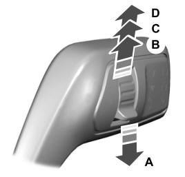
A - Single wipe.