Ford Explorer: Second Row Seats / Removal and Installation - Second Row Single Seat Cushion Cover
Special Tool(s) / General Equipment
| Interior Trim Remover |
Removal
NOTE: LH (left hand) seat shown, RH (right hand) seat similar.
NOTE: Base vehicle shown, police vehicle similar.
-
Remove the second row seat.
Refer to: Second Row Seat (501-10B Second Row Seats, Removal and Installation).
Refer to: Second Row Seat - Police (501-10B Second Row Seats, Removal and Installation).
-
-
Remove the second row seat recline handle retaining clip.
-
Remove the second row seat recline handle.
-
Remove the second row seat recline handle retaining clip.
.jpg) |
Base vehicle
-
Remove the second row seat center valance.
-
Release the retainer.
-
Release the retainer.
-
Release the retainer.
.jpg) |
-
Remove the second row seat outboard side shield.
-
Remove the screw.
-
Detach the retainers.
Use the General Equipment: Interior Trim Remover
-
Lift the side shield and pull outward.
-
Lift the side shield and pull outward.
-
Push the side shield forward.
-
Remove the screw.
.jpg) |
-
Remove the second row seat inboard side shield.
-
Remove the screw.
-
Detach the retainers.
Use the General Equipment: Interior Trim Remover
-
Lift the side shield and pull outward.
-
Lift the side shield and pull outward.
-
Push the side shield forward.
-
Remove the screw.
.jpg) |
All vehicles
-
If equipped.
Disconnect the second row single seat cushion heater mat electrical connector and release the retainers.
.jpg) |
-
-
Release the second row single seat cushion cover hook-and-loop retainer.
-
Detach the second row single seat cushion cover J-clips.
-
Release the second row single seat cushion cover hook-and-loop retainer.
.jpg) |
-
Remove the second row single seat cushion cover and foam.
.jpg) |
-
NOTICE: Use care when separating the seat cushion trim cover from the hook-and-loop strips or the hook-and-loop strips may be torn from the seat cushion foam.
NOTICE: Use care when separating the seat cushion trim cover from the hook-and arrow or the hook may be torn from the seat cushion foam.
NOTE: This step is only necessary when installing a new component.
Remove the second row single seat cushion cover.
-
Invert the cover.
-
Release the hook-and-loop strips.
-
Release the hook-and-arrows.
-
Invert the cover.
.jpg) |
Installation
-
To install, reverse the removal procedure.
 Removal and Installation - Second Row Single Seat Backrest Cover - Vehicles With: Second Row Captain Chairs
Special Tool(s) /
General Equipment
Interior Trim Remover
Removal
NOTE:
LH (left hand) seat shown, RH (right hand) seat similar.
Remove the second row seat...
 Removal and Installation - Second Row Single Seat Cushion Cover - Vehicles With: Second Row Captain Chairs
Special Tool(s) /
General Equipment
Interior Trim Remover
Removal
NOTE:
LH (left hand) seat shown, RH (right hand) seat similar.
Remove the second row seat...
Other information:
Ford Explorer 2020-2025 Service Manual: Removal and Installation - Third Row Seat Backrest Cover
Special Tool(s) / General Equipment Flat-Bladed Screwdriver Interior Trim Remover Removal NOTE: LH (left hand) shown, RH (right hand) similar. Remove the third row seat backrest. Refer to: Third Row Seat Backrest (501-10C Third Row Seats, Removal and Installation)...
Ford Explorer 2020-2025 Service Manual: Description and Operation - Rear Suspension - Overview
Overview The rear suspension consists of the following components: Coil springs Lower arm and bushing assemblies Stabilizer bar and links Toe links Upper arms Lower arm vertical links Wheel bearing and wheel hub assemblies Wheel knuckles Wheel studs Suspension height sensor Dynamically controlled shock absorbers The rear suspension uses..
Categories
- Manuals Home
- 6th Generation Explorer Owners Manual
- 6th Generation Explorer Service Manual
- Interior Trim and Ornamentation
- Description and Operation - Jacking and Lifting - Overview
- Description and Operation - Identification Codes
- New on site
- Most important about car
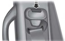
Seatbelt Height Adjustment
WARNING: Position the seatbelt height adjuster so that the seatbelt rests across the middle of your shoulder. Failure to adjust the seatbelt correctly could reduce its effectiveness and increase the risk of injury in a crash.

