Ford Explorer: Fuel Charging and Controls - 2.3L EcoBoost (201kW/273PS) / Removal and Installation - High-Pressure Fuel Pump
Removal
NOTICE:
Fuel injection equipment is manufactured to very precise
tolerances and fine clearances. To prevent fuel system damage, it is
essential that absolute cleanliness is observed when working with these
components.
NOTICE:
Do not loosen any fittings or plugs on the high-pressure fuel pump.
-
With the vehicle in NEUTRAL, position it on a hoist.
Refer to: Jacking and Lifting - Overview (100-02 Jacking and Lifting, Description and Operation).
-
Release the fuel system pressure.
Refer to: Fuel System Pressure Release (310-00A Fuel System - General Information - 2.3L EcoBoost (201kW/273PS), General Procedures).
-
Disconnect the battery.
Refer to: Battery Disconnect and Connect (414-01 Battery, Mounting and Cables, General Procedures).
-
Remove the intake manifold.
Refer to: Intake Manifold (303-01 Engine - 2.3L EcoBoost (201kW/273PS))
.
-
Disconnect the high-pressure fuel pump electrical connector and the sensor connector.
-
NOTE:
When removing or installing the high-pressure fuel
pump noise insulator, spreading the openings will reduce the risk of
damage.
Remove the high-pressure fuel pump noise insulator.
-
Disconnect the electrical connector, then detach the wiring harness retainers and move out of the way.
-
Remove the nuts, then remove the bracket.
-
NOTICE:
To release the fuel pressure in the high-pressure
fuel tube, wrap the high-pressure fuel pump flare nut with a shop towel
to absorb any residual fuel pressure during the loosening of
high-pressure fuel pump flare nut.
Remove the high-pressure fuel tube bracket bolt and
studbolt. Loosen the high-pressure fuel tube flare nuts, then
disconnect, remove and discard the high-pressure fuel tube.
-
Disconnect the high-pressure fuel pump fuel feed tube quick release coupling.
Refer to: Quick Release Coupling (310-00A Fuel System - General Information - 2.3L EcoBoost (201kW/273PS), General Procedures).
-
-
Alternately loosen the high-pressure fuel pump bolts
one complete revolution at a time. Remove and discard the high-pressure
fuel pump bolts.
-
Remove the high-pressure fuel pump and the mounting plate.
-
Remove and discard the high-pressure fuel pump O-ring seal.
-
Remove the high-pressure fuel pump tappet.
Installation
-
Inspect the high-pressure fuel pump roller tappet. If
any flat spots or scoring are found, especially in the indicated areas,
then inspect the high-pressure fuel pump and the high-pressure fuel pump
roller tappet drive lobe. Install new components as needed.
-
NOTICE:
Only rotate the crankshaft Clockwise (CW) or damage to the engine may occur.
NOTE:
The cam lobe for the high-pressure fuel pump must be at BDC for the high-pressure fuel pump installation.
Using the crankshaft pulley bolt, turn the crankshaft until the high-pressure fuel pump cam lobe is at BDC.
-
Apply clean engine oil to the high-pressure fuel pump drive unit bore and the drive lobe and the roller tappet.
Refer to: Specifications (303-01C Engine - 3.3L Duratec-V6, Specifications).
-
NOTICE:
The roller tappet's roller goes down towards the camshaft.
NOTE:
Align the notch on the high-pressure fuel pump
tappet and with the groove in the high-pressure fuel pump drive unit
bore.
Install the high-pressure fuel pump tappet.
-
Apply clean engine oil to the new high-pressure fuel
pump O-ring seal. Install a new high-pressure fuel pump O-ring seal.
Refer to: Specifications (303-01C Engine - 3.3L Duratec-V6, Specifications).
-
NOTE:
Install new high-pressure fuel pump bolts.
Install the high-pressure fuel pump and the new
high-pressure fuel pump bolts. Alternately tighten each bolt 1/2 of a
revolution until seated, then tighten in the following 2 stages.
Torque:
Stage 1:
Tighten to: :
44 lb.in (5 Nm)
Stage 2:
Tighten an additional: :
55°
-
Connect the high-pressure fuel pump fuel feed tube quick release coupling.
Refer to: Quick Release Coupling (310-00A Fuel System - General Information - 2.3L EcoBoost (201kW/273PS), General Procedures).
-
NOTE:
Make sure that a new high-pressure fuel tube is installed.
-
Install the new high-pressure fuel tube and the
bracket bolt and studbolt, then tighten the high pressure fuel tube
flare nuts and the bracket bolt and studbolt only finger tight at this
stage.
-
Calculate the correct torque wrench setting for the
following torque using the Torque Wrench Adapter Formulas.
Torque:
High pressure fuel tube flare nuts, :
Stage 1:
Tighten to: :
62 lb.in (7 Nm)
Stage 2:
Tighten to: :
89 lb.in (10 Nm)
Stage 3:
Tighten an additional: :
38°
High-pressure fuel tube bracket bolt and studbolt, tighten to: :
97 lb.in (11 Nm)
-
Install the bracket, then install and tighten the nuts.
Torque:
97 lb.in (11 Nm)
-
Connect the electrical connector, then attach the wiring harness retainers.
-
NOTE:
When removing or installing the high-pressure fuel
pump noise insulator, spreading the openings will reduce the risk of
damage.
Install the high-pressure fuel pump noise insulator.
-
Connect the high-pressure fuel pump electrical connector and the sensor connector.
-
Install the intake manifold.
Refer to: Intake Manifold (303-01 Engine - 2.3L EcoBoost (201kW/273PS))
.
-
Connect the battery.
Refer to: Battery Disconnect and Connect (414-01 Battery, Mounting and Cables, General Procedures).
-
Pressurize the fuel system.
Refer to: Fuel System Pressure Release (310-00A Fuel System - General Information - 2.3L EcoBoost (201kW/273PS), General Procedures).
Special Tool(s) /
General Equipment
303-1567Sizer, Teflon SealTKIT-2010C-FLM
307-005
(T59L-100-B)
Slide Hammer
310-205Fuel Injector Brush
310-206Remover, Fuel InjectorTKI..
Removal
Remove the valve cover.
Refer to: Valve Cover (303-01A Engine - 2.3L EcoBoost (201kW/273PS), Removal and Installation).
Remove the high-pressure fuel pump drive un..
Other information:
Removal
NOTE:
Removal steps in this procedure may contain installation details.
Remove the liftgate trim panel.
Refer to: Liftgate Trim Panel (501-05 Interior Trim and Ornamentation, Removal and Installation).
Disconnect the washer hose and the electrical connector...
O..
Categories
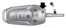
Use the key blade to start your vehicle and unlock or lock the driver door from
outside your vehicle. The integrated keyhead transmitter functions as a programmed
ignition key that operates all the locks and starts your vehicle, as well as a remote
control.
read more
.jpg)
.jpg)
.jpg)
.jpg)
.jpg)
.jpg)
.jpg)
.jpg)
.jpg)
.jpg)
.jpg)
.jpg)
.jpg)
.jpg)
.jpg)
 Removal and Installation - Fuel Rail
 Removal and Installation - High-Pressure Fuel Pump Drive Unit