Ford Explorer: Fuel Charging and Controls - 2.3L EcoBoost (201kW/273PS) / Removal and Installation - Fuel Rail
Special Tool(s) / General Equipment
.jpg) |
303-1567 Sizer, Teflon Seal TKIT-2010C-FLM |
.jpg) |
307-005
(T59L-100-B)
Slide Hammer |
.jpg) |
310-205 Fuel Injector Brush |
.jpg) |
310-206 Remover, Fuel Injector TKIT-2009A-FLM |
.jpg) |
310-207 Installer, Fuel Injector Seal Assembly TKIT-2009A-FLM |
Removal
NOTICE: Fuel injection equipment is manufactured to very precise tolerances and fine clearances. To prevent fuel system damage, it is essential that absolute cleanliness is observed when working with these components.
-
Release the fuel system pressure.
Refer to: Fuel System Pressure Release (310-00A Fuel System - General Information - 2.3L EcoBoost (201kW/273PS), General Procedures).
-
Disconnect the battery.
Refer to: Battery Disconnect and Connect (414-01 Battery, Mounting and Cables, General Procedures).
-
Remove the intake manifold.
Refer to: Intake Manifold (303-01 Engine - 2.3L EcoBoost (201kW/273PS)) .
-
Disconnect the high-pressure fuel pump electrical connector and the sensor connector.
.jpg) |
-
NOTE: When removing or installing the high-pressure fuel pump noise insulator, spreading the openings will reduce the risk of damage.
Remove the high-pressure fuel pump noise insulator.
.jpg) |
-
Disconnect the electrical connector, then detach the wiring harness retainers and move out of the way.
.jpg) |
-
Remove the nuts, then remove the bracket.
.jpg) |
-
NOTICE: To release the fuel pressure in the high-pressure fuel tube, wrap the high-pressure fuel pump flare nut with a shop towel to absorb any residual fuel pressure during the loosening of high-pressure fuel pump flare nut.
Remove the high-pressure fuel tube bracket bolt and studbolt. Loosen the high-pressure fuel tube flare nuts, then disconnect, remove and discard the high-pressure fuel tube.
.jpg) |
-
NOTE: An enhanced hexalobular or torx plus bit must be used.
Remove the bolt, then remove the shield.
.jpg) |
-
-
Detach the wire harness retainers from the fuel rail.
-
Remove the fuel rail insulator.
-
Detach the wire harness retainers from the fuel rail.
.jpg) |
-
-
Disconnect the wire harness retainer from the fuel rail.
-
Disconnect the fuel rail pressure sensor electrical connector.
-
Move the fuel rail wire harness out of the way.
-
Disconnect the wire harness retainer from the fuel rail.
.jpg) |
-
NOTICE: Pull out the fuel rails in the direction of the fuel injector axis or damage may occur to the fuel injectors.
NOTE: When removing the fuel rails, the fuel injectors may remain in the cylinder head and require the use of a Fuel Injector Remover tool to extract. Wiggling the injector and twisting the injector by hand to break it loose may allow the injector to be removed.
-
Use compressed air to remove any dirt or foreign
material from the cylinder head, block and the general surrounding area
of the fuel rail and the injectors.
-
Remove and discard the bolts, then remove the fuel rail.
-
Use compressed air to remove any dirt or foreign
material from the cylinder head, block and the general surrounding area
of the fuel rail and the injectors.
.jpg) |
-
Remove the fuel injectors from the fuel rail.
.jpg) |
-
Remove and discard the fuel injector clips.
.jpg) |
-
NOTICE: Use minimal force to remove the fuel injectors with the Fuel Injector Remover tool or damage to the fuel injector assembly may occur. Wiggling the injector and twisting by hand to break it loose may allow the injector to be removed.
NOTE: Commercially available OTC 5028 8-1/2" long slide hammer may be substituted for 307-005 where there are clearance concerns.
Using the special tools, remove any of the fuel injectors that remained in the cylinder head.
Use Special Service Tool: 307-005 (T59L-100-B) Slide Hammer. , 310-206 Remover, Fuel Injector.
.jpg) |
-
NOTICE: Do not use compressed air to clean the tip of the fuel injector.
NOTICE: Do not use a brush to clean the tip of the fuel injector.
-
Thoroughly clean any residual fuel or foreign
material from the cylinder head, the engine block and the general
surrounding area of the fuel rails and the injectors.
-
Using the special tool, clean the cylinder head fuel injector bores.
Use Special Service Tool: 310-205 Fuel Injector Brush.
-
Thoroughly clean any residual fuel or foreign
material from the cylinder head, the engine block and the general
surrounding area of the fuel rails and the injectors.
.jpg) |
-
NOTE: Note the correct orientation of the fuel injector support rings for correct installation.
Remove and discard the fuel injector O-rings. Remove and discard the fuel injector support rings.
.jpg) |
-
NOTICE: Use care when removing the lower Teflon® seals, not to scratch, nick or gouge the fuel injectors.
NOTICE: Do not attempt to cut the lower Teflon® seal without first pulling it away from the fuel injector or damage to the injector may occur.
-
Pull the lower Teflon® seal away from the injector.
-
Carefully cut and discard the lower fuel injector Teflon® seal.
-
Pull the lower Teflon® seal away from the injector.
.jpg) |
Installation
-
NOTICE: Do not lubricate the new lower Teflon® fuel injector seals.
-
Install the Teflon® Seal Guide onto the fuel injector tip.
Use Special Service Tool: 310-207 Installer, Fuel Injector Seal Assembly.
-
NOTICE: Once the Teflon® seal is installed on the Teflon® Seal Guide, it should immediately be installed onto the fuel injector to avoid excessive expansion of the Teflon® seal.
NOTE: Make sure that new lower fuel injector Teflon® seals are installed.
Install the new Teflon® seals onto the Teflon® Seal Guide, using the Pusher Tool, slide the Teflon® seals along the Teflon® Seal Guide.
-
Using the Pusher Tool, slide the Teflon® seals off
of the Teflon® Seal Guide and into the groove on the fuel injectors.
Use Special Service Tool: 310-207 Installer, Fuel Injector Seal Assembly.
-
Remove the special tools.
-
Install the Teflon® Seal Guide onto the fuel injector tip.
.jpg) |
-
NOTE: Make sure the Teflon® seal is fully seated in the groove on the fuel injector before sizing the Teflon® seal.
-
Massage and warm the Teflon® seal with your fingers
before the Teflon® seal sizer tool is installed. This will aid in
installing the Teflon® seal sizer tool.
-
NOTE: The beveled opening of the Teflon® seal sizer tool goes away from the seal.
Position the Teflon® seal sizer tool with the larger opening towards the Teflon® seal. Push while turning the Teflon® seal sizer tool 180 degrees.
Use Special Service Tool: 303-1567 Sizer, Teflon Seal.
-
Once the Teflon® seal sizer tool is installed, check
and make sure the Teflon® seal is in the sizing portion of the Teflon®
seal sizer tool.
-
After one minute, turn the Teflon® seal sizer tool back 180 degrees and remove.
-
Massage and warm the Teflon® seal with your fingers
before the Teflon® seal sizer tool is installed. This will aid in
installing the Teflon® seal sizer tool.
.jpg) |
-
NOTE: Make sure that new fuel injector support rings and new fuel injector O-ring seals are installed.
-
NOTICE: The new the fuel injector support rings must be installed in the correct orientation with the wide surface area facing up against the fuel injector O-ring seals. Improperly installed support rings may cause the fuel system to leak.
Install the new the fuel injector support rings.
-
NOTE: Do not lubricate the new lower Teflon® fuel injector seals.
Install the new fuel injector O-rings.
-
Install the new the fuel injector clips.
-
.jpg) |
-
NOTE: The anti-rotation finger of the fuel injector clip must slip into the groove of the fuel rail cup.
Install the fuel injectors to the fuel rail.
|
-
NOTE: Do not lubricate the new lower Teflon® fuel injector seals.
-
NOTE: No sudden impact force is allowed.
Press the fuel rail down into the cylinder head injector bores by hand, then install and hand start new bolts 3 and 4.
-
Release the force before tightening.
-
Install the remaining new bolts. Tighten all of the
fuel rail bolts in the sequence shown and in the following 5 stages.
Torque:
Stage 1: Tighten to: : 89 lb.in (10 Nm)
Stage 2: Back off to: : 0 lb.in (0 Nm)
Stage 3: Wait 5 s
Stage 4: Tighten to: : 124 lb.in (14 Nm)
Stage 5: Tighten an additional: : 30°
-
.jpg) |
-
-
Install the fuel rail wire harness, connect the wire harness retainer to the fuel rail.
-
Connect the fuel rail pressure sensor electrical connector.
-
Install the fuel rail wire harness, connect the wire harness retainer to the fuel rail.
|
-
-
Install the fuel rail insulator.
-
Attach the wire harness retainers to the fuel rail.
-
Install the fuel rail insulator.
|
-
NOTE: Align molded pin on bottom of the shield and install into boss in location.
NOTE: An enhanced hexalobular or torx plus bit must be used.
Install the shield, then install and tighten the bolt.
Torque: 18 lb.ft (25 Nm)
|
-
NOTE: Make sure that a new high-pressure fuel tube is installed.
-
Install the new high-pressure fuel tube and the
bracket bolt and studbolt, then tighten the high pressure fuel tube
flare nuts and the bracket bolt and studbolt only finger tight at this
stage.
-
Calculate the correct torque wrench setting for the
following torque using the Torque Wrench Adapter Formulas.
Torque:
High pressure fuel tube flare nuts, :
Stage 1: Tighten to: : 62 lb.in (7 Nm)
Stage 2: Tighten to: : 89 lb.in (10 Nm)
Stage 3: Tighten an additional: : 38°
High-pressure fuel tube bracket bolt and studbolt, tighten to: : 97 lb.in (11 Nm)
-
Install the new high-pressure fuel tube and the
bracket bolt and studbolt, then tighten the high pressure fuel tube
flare nuts and the bracket bolt and studbolt only finger tight at this
stage.
.jpg) |
-
Install the bracket, then install and tighten the nuts.
Torque: 97 lb.in (11 Nm)
|
-
Connect the electrical connector, then attach the wiring harness retainers.
|
-
NOTE: When removing or installing the high-pressure fuel pump noise insulator, spreading the openings will reduce the risk of damage.
Install the high-pressure fuel pump noise insulator.
|
-
Connect the high-pressure fuel pump electrical connector and the sensor connector.
|
-
Install the intake manifold.
Refer to: Intake Manifold (303-01 Engine - 2.3L EcoBoost (201kW/273PS)) .
-
Connect the battery.
Refer to: Battery Disconnect and Connect (414-01 Battery, Mounting and Cables, General Procedures).
-
Pressurize the fuel system.
Refer to: Fuel System Pressure Release (310-00A Fuel System - General Information - 2.3L EcoBoost (201kW/273PS), General Procedures).
 Removal and Installation - Fuel Pump Driver Module (FPDM)
Removal
All Vehicles
NOTE:
The fuel pump driver module is located on the
bottom side of the left front floor panel, above the sound insulation
panel...
 Removal and Installation - High-Pressure Fuel Pump
Removal
NOTICE:
Fuel injection equipment is manufactured to very precise
tolerances and fine clearances. To prevent fuel system damage, it is
essential that absolute cleanliness is observed when..
Other information:
Ford Explorer 2020-2026 Service Manual: Removal and Installation - Coolant Outlet Connector
Special Tool(s) / General Equipment Hose Clamp Remover/Installer Removal WARNING: Always allow the engine to cool before opening the cooling system. Do not unscrew the coolant pressure relief cap when the engine is operating or the cooling system is hot...
Ford Explorer 2020-2026 Service Manual: Removal and Installation - Heater Core
Removal NOTE: If a heater core leak is suspected, the heater core must be leak tested before it is removed from the vehicle. Remove the climate control housing. Refer to: Climate Control Housing (412-00 Climate Control System - General Information, Removal and Installation)...
Categories
- Manuals Home
- 6th Generation Explorer Owners Manual
- 6th Generation Explorer Service Manual
- General Service Information
- Body and Paint
- General Procedures - Brake Service Mode Activation and Deactivation
- New on site
- Most important about car
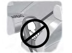
Children and Airbags
WARNING: Airbags can kill or injure a child in a child restraint. Never place a rear-facing child restraint in front of an active airbag. If you must use a forward-facing child restraint in the front seat, move the seat upon which the child restraint is installed all the way back.