Ford Explorer: Fuel Charging and Controls - 2.3L EcoBoost (201kW/273PS) / Removal and Installation - Fuel Pump Driver Module (FPDM)
Removal
All Vehicles
-
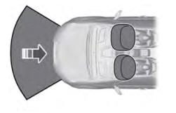
NOTE: The fuel pump driver module is located on the bottom side of the left front floor panel, above the sound insulation panel.
For fuel pump driver module component location view.
Refer to: Fuel Charging and Controls - Component Location (303-04A Fuel Charging and Controls - 2.3L EcoBoost (201kW/273PS), Description and Operation).
-
With the vehicle in NEUTRAL, position it on a hoist.
Refer to: Jacking and Lifting - Overview (100-02 Jacking and Lifting, Description and Operation).
-
If equipped, remove the fasteners and position the
front of the shield down to access the fuel pump driver module.
.jpg) |
-
If equipped, remove the fasteners and position the
front of the shield down to access the fuel pump driver module.
.jpg) |
Standard fuel pump driver module
-
Disconnect the fuel pump driver module electrical connector.
.jpg) |
-
Release the fuel pump driver module retaining tab
and then remove the fuel pump driver module from the bracket.
.jpg) |
Heavy duty fuel pump driver module
-
Disconnect the wire harness retainer, then disconnect the fuel pump driver module electrical connector.
.jpg) |
-
Remove the fuel pump driver module fasteners, then remove the fuel pump driver module.
.jpg) |
All Vehicles
-
Only if needed, remove the fasteners, then remove the fuel pump driver module bracket.
.jpg) |
Installation
All Vehicles
-
Install the fuel pump driver module bracket if removed, then install and tighten the fasteners.
Torque: 97 lb.in (11 Nm)
|
Heavy duty fuel pump driver module
-
Install the fuel pump driver module, then install and tighten the fuel pump driver module fasteners.
Torque: 97 lb.in (11 Nm)
|
-
Connect the fuel pump driver module electrical connector , then connect the wire harness retainer.
|
Standard fuel pump driver module
-
Install the fuel pump driver module to the bracket until it clicks into position.
.jpg) |
-
Connect the fuel pump driver module electrical connector.
|
All Vehicles
-
NOTE: The shield needs to be installed underneath the fender splash shield.
If equipped, install the shield, then install and tighten the fasteners.
Torque:
1, tighten to: : 22 lb.in (2.5 Nm)
2, tighten to: : 53 lb.in (6.0 Nm)
3, tighten to: : 53 lb.in (6.0 Nm)
|
-
NOTE: The shield needs to be installed underneath the fender splash shield.
If equipped, install the shield, then install and tighten the fasteners.
Torque:
Screw and washer, tighten to: : 22 lb.in (2.5 Nm)
Nut and washer tighten to: : 53 lb.in (6.0 Nm)
|
 Diagnosis and Testing - Fuel Charging and Controls
General Equipment
Ford diagnostic equipment
Diagnostics
in this manual assume a certain skill level and knowledge of
Ford-specific diagnostic practices...
 Removal and Installation - Fuel Rail
Special Tool(s) /
General Equipment
303-1567Sizer, Teflon SealTKIT-2010C-FLM
307-005
(T59L-100-B)
Slide Hammer
310-205Fuel Injector Brush
310-206Remover, Fuel InjectorTKI..
Other information:
Ford Explorer 2020-2025 Owners Manual: Declaration of Conformity
Your vehicle could have components that transmit and receive radio waves and are therefore subject to government regulation. These components must accept any interference received, including interference that could cause undesired operation. For certification labels and declarations of conformity, visit www...
Ford Explorer 2020-2025 Owners Manual: Smart Unlocks for Intelligent Access Keys (If Equipped)
This helps to prevent you from locking your key inside the passenger compartment or rear cargo area. When you electronically lock your vehicle with any door open, the transmission in park (P) and the ignition off, the system searches for an intelligent access key in the passenger compartment after you close the last door...
Categories
- Manuals Home
- 6th Generation Explorer Owners Manual
- 6th Generation Explorer Service Manual
- General Procedures - Transmission Fluid Drain and Refill
- Traction Control
- Engine - 2.3L EcoBoost (201kW/273PS)
- New on site
- Most important about car
Driver and Passenger Airbags
WARNING: Do not place your arms on the airbag cover or through the steering wheel. Failure to follow this instruction could result in personal injury.
WARNING: Keep the areas in front of the airbags free from obstruction. Do not affix anything to or over the airbag covers. Objects could become projectiles during airbag deployment or in a sudden stop. Failure to follow this instruction could result in personal injury or death.
WARNING: Airbags can kill or injure a child in a child restraint. Never place a rear-facing child restraint in front of an active airbag. If you must use a forward-facing child restraint in the front seat, move the seat upon which the child restraint is installed all the way back.