Ford Explorer: Front Seats / Removal and Installation - Front Head Restraint Guide Sleeve
Special Tool(s) / General Equipment
| Flat-Bladed Screwdriver |
Removal
NOTE: Typical head restraint guide sleeve shown, others similar.
Vehicles with police package
-
Remove the front head restraint.
-
Position the front seat backrest cover to access the guide sleeve retainer.
-
Remove the guide sleeve retainer.
-
Depress the locking tab.
-
Remove the front head restraint.
-
Position the front seat backrest cover to access the guide sleeve retainer.
.jpg) |
Vehicles without police package
-
Remove the front head restraint.
-
Depress the locking tab.
-
Remove the front head restraint.
-
Depress the locking tab.
.jpg) |
All
-
NOTE: Follow the unique instructions or graphics for this step in installation.
Remove and discard the front head restraint guide sleeve(s).
-
Release the tab.
-
Remove and discard the front head restraint guide sleeve(s).
Use the General Equipment: Flat-Bladed Screwdriver
-
Release the tab.
.jpg) |
Installation
-
NOTICE: Always install new head restraint guide sleeves. Difficult adjustment of the head restraint may occur. Failure to follow these instructions may result in component failure.
NOTICE: The head restraint guide sleeves are not interchangeable. Failure to install the correct head restraint guide sleeves at the correct position may result in component failure.
Allow the head restraint guide sleeve to slide freely through the backrest foam and backrest trim cover. Using hand pressure, twist the head restraint guide sleeve while pushing it into the backrest frame until the tab is locked into placed.
.jpg) |
-
Install the front head restraint.
-
Depress the locking tab.
-
Install the front head restraint.
-
Depress the locking tab.
.jpg) |
 Removal and Installation - Driver Multi-Contour Seat Module [SCMG]
Special Tool(s) /
General Equipment
Interior Trim Remover
Removal
NOTE:
Driver seat SCMG (driver multi-contour seat module) shown,
passenger seat SCMH (passenger multi-contour seat modu..
 Removal and Installation - Front Seat
Removal
WARNING:
The following procedure describes critical repair steps
required for correct seat component installation. Follow all notes and
steps carefully...
Other information:
Ford Explorer 2020-2026 Service Manual: Removal and Installation - Transmission Fluid Pump Idler Gear
Special Tool(s) / General Equipment 205-1018Installation Tube 307-003 (T57L-500-B) Holding Fixture, Transmission 307-091Handle, Torque ConverterTKIT-2009TC-F 307-346 (T97T-7902-A) Retainer, Torque ConverterTKIT-1998-LM (NavigatoR)TKIT-1997-F/FLM/LT 307-736Installer, Pump Drive Gear Bearing 307-737Press Tool, Oil Pump Drive Idler Gear 307-743Remo..
Ford Explorer 2020-2026 Service Manual: General Procedures - Air Conditioning (A/C) System Recovery, Evacuation and Charging - Vehicles With: R1234YF Refrigerant
Special Tool(s) / General Equipment Air Conditioning Service Unit Refrigerant Identification Equipment Recovery NOTICE: Use an A/C refrigerant analyzer before recovering any of the vehicle's A/C refrigerant. Failure to do so puts the shop's bulk refrigerant at risk of contamination...
Categories
- Manuals Home
- 6th Generation Explorer Owners Manual
- 6th Generation Explorer Service Manual
- Removal and Installation - All-Wheel Drive (AWD) Module
- Fuel Filler Funnel Location & Running Out of Fuel
- Interior Trim and Ornamentation
- New on site
- Most important about car
Locking and Unlocking
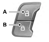
You can use the power door lock control or the remote control to lock and unlock your vehicle.
Power Door Locks
The power door lock control is on the driver and front passenger door panels.

