Ford Explorer: Handles, Locks, Latches and Entry Systems / Removal and Installation - Front Door Latch
Removal
NOTE: LH (left-hand) side shown, RH (right-hand) side similar.
NOTE: Removal steps in this procedure may contain installation details.
-
Remove the front door window regulator and motor.
Refer to: Front Door Window Regulator and Motor (501-11 Glass, Frames and Mechanisms, Removal and Installation).
-
Remove the exterior front door handle.
Refer to: Exterior Front Door Handle (501-14 Handles, Locks, Latches and Entry Systems, Removal and Installation).
-
If equipped.
Remove the door lock cylinder.
-
If equipped.
Release the door lock cylinder retaining tab.
-
If equipped.
Remove the door lock cylinder.
-
If equipped.
.jpg) |
-
Remove the screw from the exterior front door handle reinforcement.
Torque: 62 lb.in (7 Nm)
.jpg) |
-
Remove the front door glass run and bracket bolts.
Torque: 19 lb.in (2.2 Nm)
.jpg) |
-
Disconnect the electrical connectors.
-
If equipped.
Disconnect the keyless entry keypad electrical connector.
-
Disconnect the front door latch electrical connector.
-
Disconnect the front door latch jumper harness electrical connector.
-
If equipped.
.jpg) |
-
Remove the front door latch bolts.
Torque: 71 lb.in (8 Nm)
.jpg) |
-
Remove the front door latch.
.jpg) |
-
NOTE: This step is only necessary when installing a new component.
Release the cable tension by turning the release screw until the handle lever releases from the stop.
-
Turn the release screw until the handle lever releases from the stop.
-
Release the handle lever from the stop.
-
Turn the release screw until the handle lever releases from the stop.
.jpg) |
-
NOTE: This step is only necessary when installing a new component.
Remove the exterior front door handle reinforcement.
-
Press the locking tab down.
-
If equipped.
Disconnect the door lock cylinder rod.
-
Release the cable from the routing clips and detach the exterior front door handle reinforcement.
-
Detach the cable from the exterior front door handle reinforcement cable bracket.
-
Remove the cable eyelet from the lever.
-
Press the locking tab down.
.jpg) |
-
NOTE: This step is only necessary when installing a new component.
Remove the front door glass run and bracket.
-
Release the exterior front door handle reinforcement handle cable from the routing tabs.
-
Disconnect and remove the front door latch harness electrical connector.
-
Release the front door glass run and bracket retaining tabs.
-
Remove the front door glass run and bracket from the front door latch.
-
Release the exterior front door handle reinforcement handle cable from the routing tabs.
.jpg) |
-
NOTE: This step is only necessary when installing a new component.
Remove the front door latch lock rod.
.jpg) |
-
NOTE: This step is only necessary when installing a new component.
Remove the exterior front door handle reinforcement to front door latch cable access cover.
.jpg) |
-
NOTE: This step is only necessary when installing a new component.
Remove the exterior front door handle reinforcement to front door latch cable.
.jpg) |
-
NOTE: This step is only necessary when installing a new component.
Remove the interior front door handle cable and lock indicator cable access covers.
-
Remove the lock indicator cable access cover.
-
Remove the interior front door handle cable access cover.
-
Remove the lock indicator cable access cover.
.jpg) |
-
NOTE: This step is only necessary when installing a new component.
Remove the interior front door handle cable and lock indicator cable.
-
Remove the lock indicator cable.
-
Remove the interior front door handle cable.
-
Remove the lock indicator cable.
.jpg) |
Installation
-
To install, reverse the removal procedure.
-
NOTE: This step is only necessary when installing a new component.
NOTE: This step must be done correctly or the exterior door handle will not engage the lever on installation.
Position the exterior front door handle reinforcement in the service position.
-
While keeping tension on the cable and holding the handle lever in the engaged position against the stop.
-
Turn the release screw until the handle lever is positioned against the stop.
-
While keeping tension on the cable and holding the handle lever in the engaged position against the stop.
.jpg) |
-
Carry out the power door window initialization.
Refer to: Power Door Window Initialization (501-11 Glass, Frames and Mechanisms, General Procedures).
 Removal and Installation - Exterior Rear Door Handle Reinforcement
Removal
NOTE:
LH (left-hand) side shown, RH (right-hand) side similar.
Remove the rear door latch.
Refer to: Rear Door Latch (501-14 Handles, Locks, Latches and Entry Systems, Removal a..
 Removal and Installation - Front Door Lock Control Switch
Removal
NOTE:
LH (left-hand) side shown, RH (right-hand) side similar.
Remove the front door trim panel.
Refer to: Front Door Trim Panel (501-05 Interior Trim and Ornamentation, Removal..
Other information:
Ford Explorer 2020-2026 Service Manual: Description and Operation - Battery and Cables - Overview
O..
Ford Explorer 2020-2026 Service Manual: General Procedures - Elevation System Check
Check Turn the ignition ON, engine OFF. Set the parking brake. Place the gearshift in REVERSE (R) for rear parking aid sensors. Place the gearshift in DRIVE (D) for front parking aid sensors...
Categories
- Manuals Home
- 6th Generation Explorer Owners Manual
- 6th Generation Explorer Service Manual
- Body and Paint
- General Procedures - Rear Camber Adjustment
- Interior Trim and Ornamentation
- New on site
- Most important about car
Windshield Wipers
 Push the lever up or down to operate
the windshield wipers.
Push the lever up or down to operate
the windshield wipers.
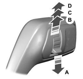
A - Single wipe.