
Ford Explorer: Climate Control System - General Information / Removal and Installation - Condenser - 2.3L EcoBoost (201kW/273PS)
Ford Explorer 2020-2026 Service Manual / Electrical / Climate Control System / Climate Control System - General Information / Removal and Installation - Condenser - 2.3L EcoBoost (201kW/273PS)
Removal
NOTICE: During the removal of components, cap, tape or otherwise appropriately protect all openings to prevent the ingress of dirt or other contamination. Remove protective materials prior to installation.
NOTE: Removal steps in this procedure may contain installation details.
-
Recover the refrigerant. Refer to the appropriate Recovery procedure in Group 412.
-
Remove the CAC.
Refer to: Charge Air Cooler (CAC) (303-12A Intake Air Distribution and Filtering - 2.3L EcoBoost (201kW/273PS), Removal and Installation).
-
Remove the condenser inlet and outlet line nuts and disconnect the fittings.
-
Make sure to cover any open ports to prevent debris from entering the system.
Torque:
1: 80 lb.in (9 Nm)
2: 133 lb.in (15 Nm)
-
Make sure to cover any open ports to prevent debris from entering the system.
.jpg) |
-
Position aside the radiator deflectors.
.jpg) |
-
-
Remove the condensor mounting bolt.
Torque: 80 lb.in (9 Nm)
-
Squeeze the locking tabs to release the condensor for removal.
-
Lift up and outward to remove the condensor.
-
Remove the condensor mounting bolt.
.jpg) |
Installation
-
To install, reverse the removal procedure.
-
NOTICE: Only use the specified material to lubricate the seals.
Install and lubricate new O-ring seals. Refer to the appropriate Specifications in Group 412.
-
Lubricate the refrigerant system with the correct amount
of clean PAG oil. Refer to the appropriate Refrigerant Oil Adding
procedure in Group 412.
 Removal and Installation - Climate Control Housing
Special Tool(s) /
General Equipment
Interior Trim Remover
Removal
NOTE:
Removal steps in this procedure may contain installation details...
 Removal and Installation - Condenser Inlet Line - 2.3L EcoBoost (201kW/273PS)
Removal
NOTICE:
During the removal of components, cap, tape or otherwise
appropriately protect all openings to prevent the ingress of dirt or
other contamination...
Other information:
Ford Explorer 2020-2026 Service Manual: General Procedures - Front Door Alignment
Adjustment NOTE: Removal steps in this procedure may contain installation details. NOTE: LH side shown, RH side similar. All alignments Open the door. Remove the bolts and the striker assembly...
Ford Explorer 2020-2026 Service Manual: Removal and Installation - Driver Airbag
Removal WARNING: The following procedure prescribes critical repair steps required for correct restraint system operation during a crash. Follow all notes and steps carefully. Failure to follow step instructions may result in incorrect operation of the restraint system and increases the risk of serious personal injury or death in a crash...
Categories
- Manuals Home
- 6th Generation Explorer Owners Manual
- 6th Generation Explorer Service Manual
- Engine - 2.3L EcoBoost (201kW/273PS)
- General Procedures - Rear Camber Adjustment
- General Procedures - Transmission Fluid Drain and Refill
- New on site
- Most important about car
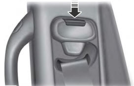
Seatbelt Height Adjustment
WARNING: Position the seatbelt height adjuster so that the seatbelt rests across the middle of your shoulder. Failure to adjust the seatbelt correctly could reduce its effectiveness and increase the risk of injury in a crash.

Copyright © 2026 www.foexplorer.com