Ford Explorer: Driveshaft / Disassembly and Assembly - Driveshaft Center Bearing
Special Tool(s) / General Equipment
| Hydraulic Press | |
| Bearing Separator |
Materials
| Name | Specification |
|---|---|
| Motorcraft® Premium Long-Life Grease XG-1-E1 |
ESA-M1C75-B |
DISASSEMBLY
-
Remove the rear driveshaft slip yoke boot.
Refer to: Rear Driveshaft Slip Yoke Boot (205-01 Driveshaft, Removal and Installation).
-
NOTE: The heat shield is to be reused unless damaged.
NOTE: Note the position of component before removal.
NOTE: This step is only necessary if replacing the center bearing.
If equipped.
Drill out the rivets and remove the heat shield from the center bearing. Discard the rivets.
.jpg) |
-
NOTE: To avoid component damage, do not clamp on the driveshaft tube.
NOTE: Take extra care not to damage the component.
Using the general equipments, remove the center bearing from the driveshaft.
Use the General Equipment: Bearing Separator
Use the General Equipment: Hydraulic Press
.jpg) |
ASSEMBLY
-
NOTICE: Do not over-lubricate the driveshaft components. Using excessive grease may damage the driveshaft components.
NOTE: Wipe off any excess grease.
Clean and lubricate the center bearing mating surface with grease.
Material: Motorcraft® Premium Long-Life Grease / XG-1-E1 (ESA-M1C75-B)
.jpg) |
-
NOTE: The center bearing is serviced as a complete assembly.
Press the new center bearing assembly onto the spline yoke until it is seated against the machined shoulder.
Use the General Equipment: Hydraulic Press
.jpg) |
-
NOTICE: Do not over-lubricate the driveshaft components. Using excessive grease may damage the driveshaft components.
NOTE: Wipe off any excess grease.
Wipe off any excess grease from the splines and boot groove.
Material: Motorcraft® Premium Long-Life Grease / XG-1-E1 (ESA-M1C75-B)
.jpg) |
-
Install the rear driveshaft slip yoke boot.
Refer to: Rear Driveshaft Slip Yoke Boot (205-01 Driveshaft, Removal and Installation).
-
NOTE: Make sure that the components are installed to the position noted before removal.
If removed.
Attach the center bearing heat shield and install the new rivets.
.jpg) |
 Disassembly and Assembly - Driveshaft Alignment Bushing
Special Tool(s) /
General Equipment
Three Leg Puller
Punch
Copper Hammer
Vise
Materials
Name
Specification
Motorcraft® Premium Long-Life GreaseXG-1-E1
ESA-M1C75-B&nb..
 Disassembly and Assembly - Driveshaft Universal Joint
Special Tool(s) /
General Equipment
205-086
(T74P-4635-C)
Installer/Remover, C-Frame and Screw
Materials
Name
Specification
Motorcraft® Premium Long-Life GreaseXG-1-E1
ESA-M1C7..
Other information:
Ford Explorer 2020-2026 Service Manual: Removal and Installation - Body Control Module (BCM)
Removal NOTE: Removal steps in this procedure may contain installation details. If installing a new BCM, connect a battery charger to the battery to make sure it is charged to maintain proper battery voltage. Refer to: Battery Charging (414-01 Battery, Mounting and Cables, General Procedures)...
Ford Explorer 2020-2026 Owners Manual: Lane Keeping System
WARNING: You are responsible for controlling your vehicle at all times. The system is designed to be an aid and does not relieve you of your responsibility to drive with due care and attention. Failure to follow this instruction could result in the loss of control of your vehicle, personal injury or death...
Categories
- Manuals Home
- 6th Generation Explorer Owners Manual
- 6th Generation Explorer Service Manual
- Body and Paint
- Removal and Installation - Front Halfshaft Speed Sensor
- Automatic Transmission - 10-Speed Automatic Transmission – 10R60
- New on site
- Most important about car
Windshield Wipers
 Push the lever up or down to operate
the windshield wipers.
Push the lever up or down to operate
the windshield wipers.
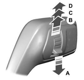
A - Single wipe.