Ford Explorer: Exterior Lighting / Diagnosis and Testing - Reversing Lamps
Diagnostic Trouble Code (DTC) Chart
Diagnostics in this manual assume a certain skill level and knowledge of Ford-specific diagnostic practices.
REFER to: Diagnostic Methods (100-00 General Information, Description and Operation).
Diagnostic Trouble Code Chart
| Module | DTC | Description | Action |
|---|---|---|---|
| BCM | B1277:11 | Reverse Lamp: Circuit Short To Ground | GO to Pinpoint Test A |
| BCM | B1277:15 | Reverse Lamp: Circuit Short To Battery or Open | GO to Pinpoint Test A |
| BCM | — | All other BCM Diagnostic Trouble Codes (DTCs) |
REFER to: Body Control Module (BCM) (419-10 Multifunction Electronic Modules, Diagnosis and Testing). |
Symptom Charts
Diagnostics in this manual assume a certain skill level and knowledge of Ford-specific diagnostic practices.
REFER to: Diagnostic Methods (100-00 General Information, Description and Operation).
Symptom Chart: Reversing Lamps
| Condition | Possible Sources | Actions |
|---|---|---|
| A module does not respond to the diagnostic scan tool |
|
REFER to: Communications Network (418-00 Module Communications Network, Diagnosis and Testing). |
| Both reversing lamps are inoperative or always on | Refer to the Pinpoint Test | GO to Pinpoint Test A |
| An individual reversing lamp is inoperative | Refer to the Pinpoint Test | GO to Pinpoint Test B |
Pinpoint Tests
.jpg) PINPOINT TEST A : BOTH REVERSING LAMPS ARE INOPERATIVE OR ALWAYS ON
PINPOINT TEST A : BOTH REVERSING LAMPS ARE INOPERATIVE OR ALWAYS ON|
Refer to Wiring Diagrams Cell 93 for schematic and connector information. Normal Operation and Fault Conditions
REFER to: Exterior Lighting - Overview (417-01 Exterior Lighting, Description and Operation). DTC Fault Trigger Conditions
Possible Sources
|
||||||||||
| A1 CHECK THE PCM (POWERTRAIN CONTROL MODULE) TRANSMISSION RANGE PID (PARAMETER IDENTIFICATION) | ||||||||||
Does the PID indicate the correct value in each gear selection?
|
||||||||||
| A2 CHECK THE REVERSING LAMP VOLTAGE CIRCUIT FOR A SHORT TO GROUND | ||||||||||
Is the resistance greater than 10,000 ohms?
|
||||||||||
| A3 CHECK THE REVERSING OUTPUT CIRCUIT FOR A SHORT TO GROUND | ||||||||||
Is the resistance greater than 10,000 ohms?
|
||||||||||
| A4 CHECK THE REVERSING LAMP VOLTAGE CIRCUITS FOR AN OPEN | ||||||||||
Is the resistance less than 3 ohms?
|
||||||||||
| A5 CHECK THE REVERSING LAMP VOLTAGE SUPPLY CIRCUIT FOR A SHORT TO VOLTAGE | ||||||||||
Are the reverse lamps still on?
|
||||||||||
| A6 CHECK THE REVERSING OUTPUT SUPPLY CIRCUIT FOR A SHORT TO VOLTAGE | ||||||||||
Is any voltage present?
|
||||||||||
| A7 CHECK FOR CORRECT BCM (BODY CONTROL MODULE) OPERATION | ||||||||||
Is the concern still present?
|
.jpg) PINPOINT TEST B : AN INDIVIDUAL REVERSING LAMP IS INOPERATIVE
PINPOINT TEST B : AN INDIVIDUAL REVERSING LAMP IS INOPERATIVE |
Refer to Wiring Diagrams Cell 93 for schematic and connector information. Normal Operation and Fault Conditions
REFER to: Exterior Lighting - Overview (417-01 Exterior Lighting, Description and Operation). Possible Sources
Visual Inspection and Pre-checks
|
||||||||||||||||
| B1 CHECK FOR VOLTAGE TO THE REVERSING LAMP | ||||||||||||||||
Is the voltage greater than 11 volts?
|
||||||||||||||||
| B2 CHECK THE REVERSING LAMP GROUND CIRCUIT FOR AN OPEN | ||||||||||||||||
Is the voltage greater than 11 volts?
|
 Diagnosis and Testing - Parking, Rear and License Plate Lamps
Diagnostic Trouble Code (DTC) Chart
Diagnostics in this manual assume a certain skill level and knowledge of Ford-specific diagnostic practices. REFER to: Diagnostic Methods (100-00 General Informati..
 Diagnosis and Testing - Stoplamps
Diagnostic Trouble Code (DTC) Chart
Diagnostics in this manual assume a certain skill level and knowledge of Ford-specific diagnostic practices. REFER to: Diagnostic Methods (100-00 General Informati..
Other information:
Ford Explorer 2020-2026 Owners Manual: Motorcraft Parts - 2.3L EcoBoost™
1 If a Motorcraft oil filter is not available, use an oil filter that meets industry performance specification SAE/USCAR-36. 2 See your authorized dealer for correct replacement. 3 For spark plug replacement, contact your authorized dealer. Replace the spark plugs at the appropriate intervals...
Ford Explorer 2020-2026 Service Manual: Removal and Installation - Air Conditioning (A/C) Pressure Transducer - 2.3L EcoBoost (201kW/273PS)
Removal NOTE: Removal steps in this procedure may contain installation details. Remove the air cleaner outlet pipe. Refer to: Air Cleaner Outlet Pipe (303-12A Intake Air Distribution and Filtering - 2.3L EcoBoost (201kW/273PS), Removal and Installation)...
Categories
- Manuals Home
- 6th Generation Explorer Owners Manual
- 6th Generation Explorer Service Manual
- General Procedures - Rear Camber Adjustment
- General Procedures - Transmission Fluid Drain and Refill
- Fuel Filler Funnel Location & Running Out of Fuel
- New on site
- Most important about car
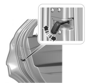
Child Safety Locks
When these locks are set, you cannot open the rear doors from the inside.

A child safety lock is on the rear edge of each rear door. You must set the child safety lock separately on each door.
Left-Hand Side

.jpg) PINPOINT TEST A : BOTH REVERSING LAMPS ARE INOPERATIVE OR ALWAYS ON
PINPOINT TEST A : BOTH REVERSING LAMPS ARE INOPERATIVE OR ALWAYS ON.jpg)
.jpg)