Ford Explorer: Exterior Lighting / Diagnosis and Testing - Autolamps
Diagnostic Trouble Code (DTC) Chart
Diagnostics in this manual assume a certain skill level and knowledge of Ford-specific diagnostic practices.
REFER to: Diagnostic Methods (100-00 General Information, Description and Operation).
Diagnostic Trouble Code Chart
| Module | DTC | Description | Action |
|---|---|---|---|
| BCM | B1A85:11 | Ambient Light Sensor: Circuit Short To Ground | GO to Pinpoint Test A |
| BCM | B1A85:13 | Ambient Light Sensor:Circuit Open | GO to Pinpoint Test A |
| BCM | — | All other BCM Diagnostic Trouble Codes (DTCs) |
REFER to: Body Control Module (BCM) (419-10 Multifunction Electronic Modules, Diagnosis and Testing). |
Symptom Charts
Symptom Chart: Autolamps
Diagnostics in this manual assume a certain skill level and knowledge of Ford-specific diagnostic practices.
REFER to: Diagnostic Methods (100-00 General Information, Description and Operation).
| Condition | Possible Sources | Actions |
|---|---|---|
| A module does not respond to the diagnostic scan tool |
|
REFER to: Communications Network (418-00 Module Communications Network, Diagnosis and Testing). |
| The autolamps are inoperative or do not operate correctly | Refer to the Pinpoint Test | GO to Pinpoint Test A |
Pinpoint Tests
|
Refer to Wiring Diagrams Cell 86 for schematic and connector information. Normal Operation and Fault Conditions
REFER to: Exterior Lighting - Overview (417-01 Exterior Lighting, Description and Operation). DTC Fault Trigger Conditions
Possible Sources
Visual Inspection and Pre-checks
|
||||||||||
| A1 CHECK THE MANUAL HEADLAMP OPERATION | ||||||||||
Do the headlamps operate correctly?
|
||||||||||
| A2 CHECK FOR VOLTAGE TO THE LIGHT SENSOR | ||||||||||
Is the voltage approximately 5 volts?
|
||||||||||
| A3 CHECK THE LIGHT SENSOR FOR GROUND | ||||||||||
Is the voltage approximately 5 volts?
|
||||||||||
| A4 CHECK THE LIGHT SENSOR GROUND CIRCUIT FOR AN OPEN | ||||||||||
Is the resistance less than 3 ohms?
|
||||||||||
| A5 CHECK THE LIGHT SENSOR INPUT CIRCUIT FOR A SHORT TO GROUND | ||||||||||
Is the resistance greater than 10,000 ohms?
|
||||||||||
| A6 CHECK THE LIGHT SENSOR INPUT CIRCUIT FOR AN OPEN | ||||||||||
Is the resistance less than 3 ohms?
|
||||||||||
| A7 CHECK THE LIGHT SENSOR INPUT CIRCUIT FOR A SHORT TO VOLTAGE | ||||||||||
Is any voltage present?
|
||||||||||
| A8 CHECK FOR CORRECT BCM (BODY CONTROL MODULE) OPERATION | ||||||||||
Is the concern still present?
|
.jpg)
.jpg)
 Description and Operation - Exterior Lighting - System Operation and Component Description
System Operation
Headlamps
System Diagram
Item
Description
1
HS-CAN2
2
BCM
3
LH low beam
4
RH low beam
5
SCCM
6
LH steerin..
 Diagnosis and Testing - Daytime Running Lamps (DRL)
Diagnostic Trouble Code (DTC) Chart
Diagnostics in this manual assume a certain skill level and knowledge of Ford-specific diagnostic practices. REFER to: Diagnostic Methods (100-00 General Informati..
Other information:
Ford Explorer 2020-2026 Service Manual: Removal and Installation - Brake Disc Shield
Removal NOTE: Removal steps in this procedure may contain installation details. Remove the brake disc. Refer to: Brake Disc (206-03 Front Disc Brake, Removal and Installation). Remove the 3 bolts and the brake disc shield...
Ford Explorer 2020-2026 Service Manual: Removal and Installation - Driver Airbag
Removal WARNING: The following procedure prescribes critical repair steps required for correct restraint system operation during a crash. Follow all notes and steps carefully. Failure to follow step instructions may result in incorrect operation of the restraint system and increases the risk of serious personal injury or death in a crash...
Categories
- Manuals Home
- 6th Generation Explorer Owners Manual
- 6th Generation Explorer Service Manual
- Automatic Transmission - 10-Speed Automatic Transmission – 10R60
- Interior Trim and Ornamentation
- General Procedures - Transmission Fluid Drain and Refill
- New on site
- Most important about car
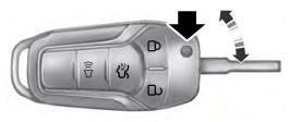
Integrated Keyhead Transmitter (If Equipped)
Use the key blade to start your vehicle and unlock or lock the driver door from outside your vehicle. The integrated keyhead transmitter functions as a programmed ignition key that operates all the locks and starts your vehicle, as well as a remote control.