Ford Explorer: Exterior Lighting / Description and Operation - Exterior Lighting - System Operation and Component Description
System Operation
Headlamps
System Diagram
.jpg)
.jpg)
| Item | Description |
|---|---|
| 1 | HS-CAN2 |
| 2 | BCM |
| 3 | LH low beam |
| 4 | RH low beam |
| 5 | SCCM |
| 6 | LH steering column multifunction switch |
| 7 | IPMA |
| 8 | GWM |
| 9 | HS-CAN1 |
| 10 | Start/Stop switch |
| 11 | HCM |
| 12 | LIN |
| 13 | LIN |
| 14 | PCM |
| 15 | LH headlamp |
| 16 | RH headlamp |
| 17 | LH front suspension height sensor |
| 18 | LH rear suspension height sensor |
| 19 | Ignition switch |
| 20 | Headlamp switch |
| 21 | (If equipped automatic headlamp leveling) |
| 22 | (without push button start) |
| 23 | (with push button start) |
| 24 | LIN |
| 25 | (North Ameria high series, police vehicles or if equipped automatic headlamp leveling) |
| 26 | LIN |
| 27 | (North Ameria except high series or police vehicles) |
Network Message Chart
BCM Network Input Messages
| Broadcast Message | Originating Module | Message Purpose |
|---|---|---|
| Headlamp flash to pass status | SCCM | Indicates to the BCM a request for the high beams or flash-to-pass. |
SCCM Network Input Messages
| Broadcast Message | Originating Module | Message Purpose |
|---|---|---|
| Auto high beam request | IPMA | Indicates to the SCCM a request for the high beams based on the IPMA camera input. |
Low Beams
The headlamp switch sends a status message over the LIN circuit to the BCM to indicate the headlamp switch status (position or a fault with the headlamp switch). The BCM turns the parking lamps and headlamps on when the ignition is in RUN and the BCM detects a fault from the headlamp switch or wiring. This is normal behavior of the BCM when a fault has been detected with the inputs from the headlamp switch.
When the BCM receives a message requesting the headlamps on, it supplies voltage to the LED control module mounted to the headlamp assembly. The LED control module sends voltage to the low beam Light Emitting Diodes (LEDs) in each headlamp assembly.
The BCM
also provides Field Effect Transistor (FET) protection of the low beam
output circuits. When an excessive current draw is detected, the BCM disables the affected circuit driver. For additional information on BCM Field Effect Transistor (FET) protection,
Refer to: Module Controlled Functions - System Operation and Component Description (419-10 Multifunction Electronic Modules, Description and Operation).
High Beams - Low Series Headlamps
The SCCM monitors the LH steering column multifunction switch for a high beam request. When the LH steering column multifunction switch is in the HIGH BEAMS position, the SCCM sends a message over the HS-CAN2 to the GWM, then the GWM sends the message to the BCM over the HS-CAN1.
The BCM supplies voltage to the LED control module mounted on each headlamp assembly when the ignition is on.
When the BCM reads a request for the high beams, it sends a message through the headlamp LIN circuit to the LED control module mounted on each headlamp assembly. The LED control module then provides the proper voltage to the high beam Light Emitting Diodes (LEDs) in each headlamp assembly.
When the low beams are on and the BCM receives a request for high beams, low beam Light Emitting Diodes (LEDs) remains powered on and the high beam Light Emitting Diodes (LEDs) are also illuminated. This changes the headlamp beam pattern to illuminate a greater distance.
The BCM
also provides Field Effect Transistor (FET) protection of the exterior
lamps switched voltage and high beam output circuits. When an excessive
current draw is detected, the BCM disables the affected circuit driver. For additional information on BCM Field Effect Transistor (FET) protection,
Refer to: Module Controlled Functions - System Operation and Component Description (419-10 Multifunction Electronic Modules, Description and Operation).
High Beams - High Series Headlamps
The SCCM monitors the LH steering column multifunction switch for a high beam request. When the LH steering column multifunction switch is in the HIGH BEAMS position, the SCCM sends a message over the HS-CAN2 to the HCM.
The BCM supplies voltage to the LED control module mounted on each headlamp assembly when the ignition is on.
When the HCM reads a request for the high beams, it sends a message through the headlamp LIN circuit to the LED control module mounted on each headlamp assembly. The LED control module then provides the proper voltage to the high beam Light Emitting Diodes (LEDs) in each headlamp assembly.
When the low beams are on and the HCM receives a request for high beams, low beam Light Emitting Diodes (LEDs) remains powered on and the high beam Light Emitting Diodes (LEDs) are also illuminated. This changes the headlamp beam pattern to illuminate a greater distance.
The BCM
also provides Field Effect Transistor (FET) protection of the exterior
lamps switched voltage and high beam output circuits. When an excessive
current draw is detected, the BCM disables the affected circuit driver. For additional information on BCM Field Effect Transistor (FET) protection,
Refer to: Module Controlled Functions - System Operation and Component Description (419-10 Multifunction Electronic Modules, Description and Operation).
Automatic High Beams - Low Series Headlamps
The automatic high beam system uses a camera to monitor surrounding traffic conditions and high beam usage. The camera is part of the IPMA. The IPMA communicates light information over the HS-CAN2 to the GWM then the GWM sends the information to the BCM over the HS-CAN1.
The automatic high beam feature is active only when the headlamp switch is in the AUTOLAMPS position.
During nighttime driving, the automatic high beam system automatically turns the high beams on if it is dark enough and no other traffic is present. When the system detects an approaching vehicle's headlamps or a preceding vehicle's rear lamps, the system turns off the high beams. When the approaching vehicle's headlamps or the preceding vehicle's rear lamps are no longer detected, the high beams automatically turn back on.
The IPMA turns the high beam headlamps on when the following conditions are met:
- The feature has been enabled using the message center
- The headlamp switch is in the AUTOLAMPS position and the autolamps feature has turned the exterior lamps on
- The vehicle speed is greater than 51 km/h (32 mph)
- The IPMA determines the ambient lighting conditions are dark enough
- The IPMA does not detect any light source that can be interpreted as an illuminated vehicle lamp
The IPMA turns the high beams off if any of the following occur:
- The IPMA detects any light source that can be interpreted as an illuminated vehicle lamp
- The IPMA determines the ambient lighting conditions are not dark enough
- The vehicle speed falls below 44 km/h (27 mph)
- The autolamps are turned off
- The IPMA determines the view is blocked
Automatic High Beams - High Series Headlamps
The automatic high beam system uses a camera to monitor surrounding traffic conditions and high beam usage. The camera is part of the IPMA. The IPMA communicates light information over the HS-CAN2 to the HCM.
The automatic high beam feature is active only when the headlamp switch is in the AUTOLAMPS position.
During nighttime driving, the automatic high beam system automatically turns the high beams on if it is dark enough and no other traffic is present. When the system detects an approaching vehicle's headlamps or a preceding vehicle's rear lamps, the system turns off the high beams. When the approaching vehicle's headlamps or the preceding vehicle's rear lamps are no longer detected, the high beams automatically turn back on.
The IPMA turns the high beam headlamps on when the following conditions are met:
- The feature has been enabled using the message center
- The headlamp switch is in the AUTOLAMPS position and the autolamps feature has turned the exterior lamps on
- The vehicle speed is greater than 51 km/h (32 mph)
- The IPMA determines the ambient lighting conditions are dark enough
- The IPMA does not detect any light source that can be interpreted as an illuminated vehicle lamp
The IPMA turns the high beams off if any of the following occur:
- The IPMA detects any light source that can be interpreted as an illuminated vehicle lamp
- The IPMA determines the ambient lighting conditions are not dark enough
- The vehicle speed falls below 44 km/h (27 mph)
- The autolamps are turned off
- The IPMA determines the view is blocked
Flash-To-Pass - Low Series Headlamps
The SCCM monitors the LH steering column multifunction switch for a flash-to-pass request. When the LH steering column multifunction switch is in the FLASH-TO-PASS position, the SCCM sends a message over the HS-CAN2 to the GWM then the GWM sends the message to the BCM over the HS-CAN1.
When the ignition is in RUN and the flash-to-pass is requested, the high beams are activated as long as the LH steering column multifunction switch is held in the flash-to-pass position.
Flash-To-Pass - High Series Headlamps
The SCCM monitors the LH steering column multifunction switch for a flash-to-pass request. When the LH steering column multifunction switch is in the FLASH-TO-PASS position, the SCCM sends a message over the HS-CAN2 to the GWM then the GWM sends the message to the BCM over the HS-CAN1 HCM.
When the ignition is in RUN and the flash-to-pass is requested, the high beams are activated as long as the LH steering column multifunction switch is held in the flash-to-pass position.
Signature Lighting
Signature lighting is a function of the LED DRL/front parking lamps. The signature lighting function illuminates the LED DRL/front parking lamps at a reduced intensity in the headlamp assembly. The signature lighting function utilities the DRL/front parking lamps circuit at a reduced voltage from the BCM to the headlamp LED control module.
Automatic Headlamp Leveling
The headlamp beam height is automatically adjusted according to vehicle load, speed, acceleration and braking data received from the ABS module and PCM.
The front lighting uses a HCM to command the up/down aiming of the headlamp adaptive lighting LED through the LIN to the headlamp assemblies. The headlamp assemblies contain a module that receives the messages through the LIN from the HCM.
Depending on the inputs received (steering wheel angle and vehicle speed for example), the HCM can command the height at which the headlamp LED is aimed (up or down) to improve nighttime visibility. Automatic headlamp leveling is activated when the headlamp switch is in the HEADLAMPS or AUTOLAMPS position.
When the LED control module first receives voltage when the ignition is on the and LED control module commands the headlamps up and down to initialize the system. During the initialization, the HCM runs diagnostics on the system and set Diagnostic Trouble Codes (DTCs) for applicable system faults.
Headlamp Exit Delay
After the ignition is off, you can switch the headlamps on by pulling the direction indicator lever toward you. A short tone is heard. The headlamps switch off automatically after three minutes with any door open or 30 seconds after the last door has been closed. This features is canceled by pulling the direction indicator toward you again or if the ignition is on again.
DRL
System Diagram
.jpg)
.jpg)
| Item | Description |
|---|---|
| 1 | BCM |
| 2 | Ignition switch |
| 3 | Headlamp switch |
| 4 | PCM |
| 5 | HS-CAN1 |
| 6 | Start/Stop switch |
| 7 | (without push button start) |
| 8 | (with push button start) |
| 9 | Low beam Light Emitting Diodes (LEDs) |
| 10 | LED DRL/Front Parking Lamps |
| 11 | (Base series headlamp headlamps) |
| 12 | (Mid and high series headlamps) |
| 13 | LIN |
DRL
For base series headlamps, the DRL system illuminates the low beam Light Emitting Diodes (LEDs) at a reduced intensity.
For mid and high series headlamps, the DRL system illuminates the LED DRL/front parking lamps at full intensity in the headlamp assembly when the ignition is on, the headlamp switch is in the OFF or AUTOLAMPS position and the headlamps have not been turned on by the autolamp system.
When the ignition is in ON, the BCM supplies voltage to each headlamp assembly.
The BCM monitors the ignition status, the headlamp switch and autolamp status.
There are two types of DRL, conventional (where it is required) and configurable.
When equipped with conventional DRL, the DRL are active in any headlamp switch position except the HEADLAMPS position.
The conventional DRL are activated when all of the following conditions are met:
- The ignition is ON.
- The headlamps switch is in OFF, PARKLAMPS or AUTOLAMPS position and the headlamps have not been turned on by the autolamp system.
- The transmission is not in PARK.
When equipped with configurable DRL, the DRL may be enabled through the IPC message center. When enabled, the DRL are active only in the AUTOLAMPS headlamp position. When autolamps request the headlamps on, the DRL are deactivated.
The configurable DRL are activated when all of the following conditions are met:
- The ignition is ON.
- The headlamps switch is in AUTOLAMPS position and the headlamps have not been turned on by the autolamp system.
- The transmission is not in PARK.
When the transmission is in not in PARK, the PCM sends a message over the HS-CAN1 to the BCM indicating the transmission is not in PARK.
The BCM also provides Field Effect Transistor (FET) protection of the DRL output circuits. When an excessive current draw is detected, the BCM disables the affected circuit driver.
Refer to: Module Controlled Functions - System Operation and Component Description (419-10 Multifunction Electronic Modules, Description and Operation).
Autolamps
System Diagram
.jpg)
.jpg)
| Item | Description |
|---|---|
| 1 | BCM |
| 2 | Light sensor |
| 3 | Low beams |
| 4 | Start/Stop switch |
| 5 | SCCM |
| 6 | GWM |
| 7 | HS-CAN1 |
| 8 | HS-CAN2 |
| 9 | Wiper/Washer switch |
| 10 | Parking lamps |
| 11 | (with pushbutton start) |
| 12 | Ignition switch |
| 13 | (without pushbutton start) |
| 14 | LIN |
| 15 | Headlamp switch |
Network Message Chart
BCM Network Input Messages
| Broadcast Message | Originating Module | Message Purpose |
|---|---|---|
| Front wiper status | SCCM | The BCM uses the wiper status information for the operation of the wiper activated headlamps feature. |
Autolamps
The BCM monitors the light sensor with a voltage signal. The light sensor input to the BCM varies with the ambient light conditions.
The BCM monitors the headlamp switch circuits to indicate the headlamp switch position.
When the BCM receives a headlamp switch status indicating a request for the autolamps, the BCM monitors the light sensor for the ambient light condition. If the BCM determines the ambient light level is dark, the BCM illuminates the exterior parking and low beam lamps
Headlamps On With Wipers On Function
When the headlamp switch is in the autolamps position, the exterior lamps turn on when the front wipers are in low or high. This feature does not activate the exterior lamps during a mist wipe, while the wipers are on to clear washer fluid during a wash condition or if the wipers are in automatic or intermittent modes.
The exterior lamps turn off when the ignition switches off, the headlamp switch is placed in the OFF position, or the front wipers are turned off. The exception to this is when the exterior lights are on because of darkness determined by the autolamp system.
Stoplamps
System Diagram
.jpg)
.jpg)
| Item | Description |
|---|---|
| 1 | BCM |
| 2 | LH rear lamp assembly |
| 3 | RH rear lamp assembly |
| 4 | Stoplamp switch |
| 5 | High mounted stoplamp |
Stoplamps
The BCM monitors the input from the stoplamp switch. When the brake pedal is applied, voltage is routed to the BCM, indicating a request for the stoplamps. The BCM then supplies voltage to the stoplamps.
The BCM uses 3 separate output circuits. The LH stoplamp output circuit, RH stoplamp output circuit and the high-mounted stoplamp output circuit.
The BCM
also provides Field Effect Transistor (FET) protection of the stoplamp
output circuits. When an excessive current draw is detected, the BCM disables the affected stoplamp circuit driver.
Refer to: Module Controlled Functions - System Operation and Component Description (419-10 Multifunction Electronic Modules, Description and Operation).
Turn Signal and Hazard Lamps
System Diagram
.jpg)
.jpg)
| Item | Description |
|---|---|
| 1 | (with push button start) |
| 2 | (without push button start) |
| 3 | HS-CAN2 |
| 4 | SCCM |
| 5 | GWM |
| 6 | HS-CAN1 |
| 7 | Start/Stop switch |
| 8 | Hazard switch |
| 9 | BCM |
| 10 | LH exterior mirror |
| 11 | RH exterior mirror |
| 12 | DDM |
| 13 | PDM |
| 14 | LH front turn lamp |
| 15 | Ignition switch |
| 16 | RH front turn lamp |
| 17 | LH rear turn lamp |
| 18 | RH rear turn lamp |
| 19 | LH steering column multifunction switch |
| 20 | MS-CAN |
Network Message Chart
BCM Network Input Messages
| Broadcast Message | Originating Module | Message Purpose |
|---|---|---|
| Turn signal switch status | SCCM | Indicates the turn signal stalk position on the LH steering column multifunction switch (left/right lane change or turn signal on or off). The BCM activates the left/right turn signals based on this input. |
DDM and PDM Network Input Messages
| Broadcast Message | Originating Module | Message Purpose |
|---|---|---|
| Turn indication request | BCM | A command to the DDM or PDM to activate/deactivate the exterior mirror turn indicator. |
Turn Signals
The SCCM monitors the LH steering column multifunction switch position. When the LH steering column multifunction switch is in the LH TURN or RH TURN position, the SCCM sends a message over the HS-CAN2 to the GWM then the GWM sends the message to the BCM over the HS-CAN1 indicating a request for the LH or RH turn signal.
For front turn lamps when the BCM receives a request for a turn signal, the BCM supplies on/off voltage to the LED control module mounted to the headlamp assembly. The LED control module send voltage to the turn lamp Light Emitting Diodes (LEDs). During normal operation, when the LED control module supplies voltage to the turn Light Emitting Diodes (LEDs), the LED control module sends the same voltage back to the BCM through the outage circuit. If the Light Emitting Diodes (LEDs) are inoperative the BCM does not receive this voltage feedback through the outage circuit.
When the BCM receives a request for a turn signal, the BCM sends a turn indicator command message over the HS-CAN1 to the GWM then the MS-CAN to the door modules for the exterior mirror turn lamps.
For rear turn lamps, when the BCM receives a request for a turn signal, the BCM supplies on/off voltage to the appropriate turn lamps.
If a front or rear turn signal lamp is inoperative, the IPC turn lamp indicator fast flashes at approximately 150 times per minute to indicate a bulb outage to the driver (the exterior turn lamps still flash at approximately 70 times per minute).
The BCM
also provides Field Effect Transistor (FET) protection of the turn lamp
output circuits. When an excessive current draw is detected, the BCM disables the affected turn lamp circuit driver.
Refer to: Module Controlled Functions - System Operation and Component Description (419-10 Multifunction Electronic Modules, Description and Operation).
Hazard Lamps
The BCM sends a voltage signal to the hazard flasher lamp switch to monitor for a hazard lamp function request. When the hazard flasher lamp switch is pressed, the voltage signal is routed to ground, indicating a request to activate or deactivate the hazard lamp function.
When the BCM receives a request for the hazard lamps, the BCM supplies on/off voltage to the front and rear turn lamps and sends a request to the door modules to flash the exterior mirror turn lamps.
Parking, Rear, and License Plate Lamps
System Diagram
.jpg)
.jpg)
| Item | Description |
|---|---|
| 1 | BCM |
| 2 | LH front parking lamps |
| 3 | Headlamp switch |
| 4 | RH front parking lamps |
| 5 | LH rear parking lamps |
| 6 | RH rear parking lamps |
| 7 | License plate lamps |
| 8 | LIN |
Parking Lamps
The headlamp switch sends a status message over the LIN circuit to the BCM to indicate the headlamp switch status (position or a fault with the headlamp switch). The BCM turns the parking lamps and headlamps on when the ignition is in RUN and the BCM detects a fault from the headlamp switch or wiring. This is normal behavior of the BCM when a fault has been detected with the inputs from the headlamp switch.
When the BCM receives a request for a parking lamps, the BCM supplies voltage to the headlamp assembly, rear parking lamps, license plate lamps and, if equipped, the reverse lamp parking lamps.
The BCM
also provides Field Effect Transistor (FET) protection of the parking
lamps output circuits. When an excessive current draw is detected, the BCM disables the affected parking lamps circuit driver.
Refer to: Module Controlled Functions - System Operation and Component Description (419-10 Multifunction Electronic Modules, Description and Operation).
Fog Lamps
System Diagram
.jpg)
.jpg)
| Item | Description |
|---|---|
| 1 | BCM |
| 2 | Headlamp switch |
| 3 | Front fog lamps |
| 4 | Ignition switch |
| 5 | Start/Stop switch |
| 6 | (without push button start) |
| 7 | (with push button start) |
| 8 | SCCM |
| 9 | GWM |
| 10 | LH steering column multifunction switch |
| 11 | HS-CAN1 |
| 12 | HS-CAN2 |
| 13 | LIN |
| 14 | Rear fog lamps |
Fog Lamps
The headlamp switch sends a status message over the LIN circuit to the BCM to indicate the headlamp switch status (position or a fault with the headlamp switch). The BCM turns the parking lamps and headlamps on when the ignition is in RUN and the BCM detects a fault from the headlamp switch or wiring. This is normal behavior of the BCM when a fault has been detected with the inputs from the headlamp switch.
When the BCM receives input from the headlamp switch indicating a request for the front fog lamps, the BCM provides voltage to the front fog lamps.
When the BCM receives input from the headlamp switch indicating a request for the rear fog lamp, the BCM provides voltage to the rear fog lamp.
The BCM
also provides an Field Effect Transistor (FET) protection of the fog
lamp output circuits. When an excessive current draw is detected, the BCM disables the fog lamp output circuit drivers.
Refer to: Module Controlled Functions - System Operation and Component Description (419-10 Multifunction Electronic Modules, Description and Operation).
Reversing Lamps
System Diagram
.jpg)
.jpg)
| Item | Description |
|---|---|
| 1 | HS-CAN1 |
| 2 | BCM |
| 3 | PCM |
| 4 | Reversing lamps |
| 5 | TR sensor |
| 6 | (without push button start) |
| 7 | (with push button start) |
| 8 | Ignition switch |
| 9 | Start/Stop switch |
Network Message Chart
BCM Network Input Messages
| Broadcast Message | Originating Module | Message Purpose |
|---|---|---|
| Reverse | PCM | Indicates the transmission is in reverse gear to the BCM. When the transmission is in REVERSE and the ignition in RUN, the BCM provides voltage to the reversing lamps. |
Reversing Lamps
When the transmission is in REVERSE, the PCM sends a message over the HS-CAN1 to the BCM indicating the transmission is in REVERSE. The BCM provides voltage to the reversing lamp when it receives the message that the transmission is in REVERSE and the ignition is in RUN.
The BCM
also provides Field Effect Transistor (FET) protection of the reversing
lamp output circuit. When an excessive current draw is detected, the BCM disables the affected reversing lamps circuit driver.
Refer to: Module Controlled Functions - System Operation and Component Description (419-10 Multifunction Electronic Modules, Description and Operation).
Trailer Lamps
System Diagram
.jpg)
.jpg)
| Item | Description |
|---|---|
| 1 | MS-CAN |
| 2 | TRM |
| 3 | Trailer tow connector |
| 4 | BCMC |
| 5 | Trailer tow reversing lamp relay |
| 6 | Trailer tow parking lamp relay |
| 7 | HS-CAN1 |
| 8 | BCM |
| 9 | Headlamp switch |
| 10 | Stoplamp switch |
| 11 | GWM |
| 12 | SCCM |
| 13 | LH steering column multifunction switch |
| 14 | HS-CAN2 |
| 15 | PCM |
| 16 | LIN |
Network Message Chart
BCM Network Input Messages
| Broadcast Message | Originating Module | Message Purpose |
|---|---|---|
| Gear position | PCM | Indicates the transmission is in reverse gear to the BCM. When the transmission is in REVERSE and the ignition in RUN, the BCM provides voltage to the reversing lamps. |
| Turn signal switch status | SCCM | Indicates the turn signal stalk position on the LH steering column multifunction switch (left/right lane change or turn signal on or off). |
TRM Network Input Messages
| Broadcast Message | Originating Module | Message Purpose |
|---|---|---|
| Turn indication request | BCM | A command to the TRM to activate/deactivate the turn indicator output to the trailer tow connector. |
| Stoplamp request | BCM | A command to the TRM to activate/deactivate the stop lamps output to the trailer tow connector. |
Trailer Stop-Turn Lamps
The SCCM monitors the LH multifunction switch position. When the LH multifunction switch is in the left or right turn position, the SCCM sends a message over the LIN to the BCM indicating a request for the LH or RH turn signal.
When the BCM receives a request for a turn signal, the BCM sends a turn indicator command message over the MS-CAN to the TRM to activate the requested turn indicator output to the trailer tow connector.
When the BCM receives input from the stoplamp switch indicating the brake pedal is being pressed, the TRM receives a stoplamp activation signal from the BCM.
Trailer Parking Lamps
The headlamp switch sends a headlamp switch status message over the LIN to the BCM to indicate the headlamp switch status (position or a fault with the headlamp switch).
When the parking lamps or headlamps position is selected, the BCM provides a ground path to the parking lamps trailer tow relay (integral to the BCMC). When the BCM provides ground the parking lamps trailer tow relay, the relay is energized and the relay provides parking lamp voltage to the trailer tow connector.
Trailer Reversing Lamps
When the transmission is in REVERSE, the PCM sends a message over the HS-CAN1 to the BCM indicating the transmission is in REVERSE. The BCM provides ground to the reversing lamps trailer tow relay (integral to the BCMC) when it receives the message the transmission is in REVERSE and the ignition is in RUN. When the BCM provides voltage to the reversing lamps trailer tow relay, the relay is energized and the relay provides reversing lamp voltage to the trailer tow connector.
Trailer Battery Charging
The TRM is supplied voltage for trailer battery charging from the BCMC.
The TRM provides voltage to the trailer tow connector for trailer battery charging when all the following are true:
- The TRM detects that a trailer is connected.
- The ignition is on and engine is running.
- A brake pedal application has been detected in the present ignition cycle.
- The BCM load shed strategy is not active (a message is displayed in the instrument cluster, such as Low Battery Features Temporarily Turned Off or Turn Power Off To Save Battery, to indicate that BCM load shed strategy is active).
Trailer And Lamp Outage Detection
The TRM detects a trailer is present when the brake pedal is pressed for approximately 2 seconds and the TRM senses resistance in the LHand RH brake/turn signal output circuits that is within a calibrated range. If the resistance is higher than the calibrated range on either the LH or RH brake/turn signal output circuits, the TRM reports a trailer lamp fault message. If the resistance is lower than the calibrated range on one of the LH or RH brake/turn signal output circuits when the brake is pressed during the ignition cycle, the TRM reports a trailer lamp fault message and the TRM sets a DTC.
Field Effect Transistor (FET) Protection
The TRM utilizes a Field Effect Transistor (FET) protective circuit strategy for its lamp output circuits. Output loads (current level) are monitored for excessive current (typically short circuits) and are shut down (turns off the voltage or ground provided by the module) when a fault event is detected.
A Field Effect Transistor (FET) is a type of transistor the control module software uses to control and monitor current flow on module outputs. The Field Effect Transistor (FET) protection strategy prevents module damage in the event of excessive current flow.
Output loads (current level) are monitored for excessive current draw (typically short circuits). When a fault event is detected the Field Effect Transistor (FET) turns off and a short circuit DTC sets. The module resets the Field Effect Transistor (FET) protection and allows the circuit to function when the fault is corrected or the ignition state is cycled off and then back on.
When the excessive circuit load occurs often enough, the module shuts down the output until a repair procedure is carried out. Each Field Effect Transistor (FET) protected circuit has 3 predefined levels of short circuit tolerance based on a module lifetime level of fault events based upon the durability of the Field Effect Transistor (FET).
When each level is reached, the DTC associated with the short circuit sets along with DTC U1000:00. These Diagnostic Trouble Codes (DTCs) can be cleared using the module on-demand self-test, then the Clear DTC operation on the scan tool (if the on-demand test shows the fault corrected). The module never resets the fault event counter to zero and continues to advance the fault event counter as short circuit fault events occur.
If the number of short circuit fault events reach the third level, then Diagnostic Trouble Codes (DTCs) U1000:00 and U3000:49 set along with the associated short circuit DTC. DTC U3000:49 cannot be cleared and the module must be replaced after the repair.
Component Description
Headlamp Assembly
The headlamps utilize a non-serviceable module (integrated into the headlamp assembly) to control the headlamp daytime running/park/turn lamps.
Exterior lamps are vented to accommodate normal changes in pressure. Condensation can be a natural by-product of this design. When moist air enters the lamp assembly through the vents, there is a possibility that condensation can occur if the temperature is cold. When normal condensation occurs, a thin mist forms on the interior of the lens. The thin mist eventually clears and exits through the vents during normal operation. The amount of time it takes to clear the lens of acceptable mist varies with ambient humidity and lamp types. Normal condensation clears from any lamp in 48 hours under dry conditions.
Do not replace a lamp assembly with acceptable levels of condensation such as:
- presence of thin mist (no streaks, drip marks or droplets are present)
- fine mist covers less than 50% of the lens
Examples of unacceptable moisture (usually caused by a lamp housing leak):
- water puddling inside the lamp
- large water droplets, drip marks or streaks present on the interior of the lens
Headlamp Switch
The headlamp switch sends a headlamp switch status message over the LIN to the BCM to indicate the headlamp switch status (position or a fault with the headlamp switch).
Light Sensor
The BCM sends a voltage signal to the light sensor. The light sensor provides resistance between the voltage signal and ground. The resistance varies depending on the amount of ambient light detected by the light sensor. The brighter the ambient light, the lower the resistance. By varying the resistance, the BCM can determine the amount of ambient light.
Stoplamp Switch
The stoplamp switch is a normally open switch and is provided voltage at all times. When the brake pedal is applied, the switch closes and routes voltage to the BCM.
 Description and Operation - Exterior Lighting - Overview
Overview
Headlamps
The LED
headlamp system is a quad-beam pattern system. It consists of
non-replaceable low and high beam Light Emitting Diodes (LEDs) in each
headlamp assembly...
 Diagnosis and Testing - Autolamps
Diagnostic Trouble Code (DTC) Chart
Diagnostics in this manual assume a certain skill level and knowledge of Ford-specific diagnostic practices. REFER to: Diagnostic Methods (100-00 General Informati..
Other information:
Ford Explorer 2020-2025 Service Manual: Removal and Installation - Rear Subframe
Special Tool(s) / General Equipment 300-OTC1585AEPowertrain Lift Vehicle/Axle Stands Wooden Block Removal NOTICE: Suspension fasteners are critical parts that affect the performance of vital components and systems. Failure of these fasteners may result in major service expense...
Ford Explorer 2020-2025 Service Manual: Description and Operation - Identification Codes
Vehicle Identification Number (VIN) VIN Locator The VIN is a 17-digit combination of letters and numbers. The VIN is stamped on a metal tab riveted to the instrument panel, top upper left of the dash. The VIN is also found on the VC label. If the VIN plate requires replacement, authorized dealers must contact their respective regional office...
Categories
- Manuals Home
- 6th Generation Explorer Owners Manual
- 6th Generation Explorer Service Manual
- Interior Trim and Ornamentation
- Traction Control
- Engine
- New on site
- Most important about car
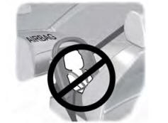
Children and Airbags
WARNING: Airbags can kill or injure a child in a child restraint. Never place a rear-facing child restraint in front of an active airbag. If you must use a forward-facing child restraint in the front seat, move the seat upon which the child restraint is installed all the way back.