Ford Explorer: Steering Column / Removal and Installation - Steering Column
Special Tool(s) / General Equipment
| Flat Headed Screw Driver |
Removal
NOTICE: To prevent damage to the clockspring, make sure the front wheels are in the straight-ahead position.
NOTICE: Precise tolerances are required when manufacturing a steering column. Never install a repaired, rebuilt, aftermarket, or remanufactured steering column. Always install a new steering column. Failure to follow this direction can result in steering column failure.
NOTE: Removal steps in this procedure may contain installation details.
All vehicles
-
Depower the SRS.
Refer to: Supplemental Restraint System (SRS) Depowering (501-20B Supplemental Restraint System, General Procedures).
-
NOTE: This step is only necessary when installing a new component.
Remove the SCCM.
Refer to: Steering Column Control Module (SCCM) (211-05 Steering Wheel and Column Electrical Components, Removal and Installation).
-
NOTE: This step is only necessary when installing a new component.
Remove the steering column shrouds.
Refer to: Steering Column Shrouds (501-05 Interior Trim and Ornamentation, Removal and Installation).
-
NOTICE: Make sure that the steering wheel does not rotate or damage to the clockspring may occur.
Secure the steering wheel.
.jpg) |
-
Release the push pin and remove the drivers side insulation panel.
-
Remove the bolts.
Torque: 28 lb.in (3.2 Nm)
-
Remove the nut.
Torque: 22 lb.in (2.5 Nm)
-
Remove the bolts.
.jpg) |
-
Remove the access cover.
.jpg) |
-
Remove the bolts, release the clips and remove the lower steering column trim panel.
-
Release the tabs and position aside the electrical connector and harness.
Torque: 17 lb.in (1.9 Nm)
-
Release the tabs and position aside the electrical connector and harness.
.jpg) |
Vehicles with selector lever
-
Disconnect the selector lever electrical connector and unclip the harness.
.jpg) |
-
Remove the screw and the selector lever.
Torque: 159 lb.in (18 Nm)
.jpg) |
-
NOTICE: Do not pull or pry on the selector lever cable or the selector lever cable end may be damaged. Use a screwdriver and turn the screwdriver as shown to pry the cable end off the post as close to the post as possible.
Using a screwdriver, pry the selector lever cable end from the selector lever mechanism.
Use the General Equipment: Flat Headed Screw Driver
.jpg) |
-
Remove the selector lever cable mount retainer and remove the selector lever cable from the bracket.
.jpg) |
Vehicles with power adjustable steering column
-
-
Release the wiring harness retainers.
-
Disconnect the steering column tilt motor and telescopic motor electrical connectors.
-
Release the wiring harness retainers.
.jpg) |
All vehicles
-
Remove and discard the steering column shaft bolt and separate the steering column shaft from the steering column..jpg) WARNING:
Do not reuse steering column shaft bolts. This
may result in fastener failure and steering column shaft detachment or
loss of steering control. Failure to follow this instruction may result
in serious injury to vehicle occupant(s).
WARNING:
Do not reuse steering column shaft bolts. This
may result in fastener failure and steering column shaft detachment or
loss of steering control. Failure to follow this instruction may result
in serious injury to vehicle occupant(s).
Torque: 22 lb.ft (30 Nm)
.jpg) |
-
Remove and discard the rear steering column mounting nuts.
WARNING:
Do not reuse steering column nuts. This may
result in fastener failure and steering column detachment or loss of
steering control. Failure to follow this instruction may result in
serious injury to vehicle occupant(s).
Torque: 18 lb.ft (25 Nm)
.jpg) |
-
NOTE: Power adjustable column shown, others similar.
Remove and discard the forward steering column mounting nuts and remove the steering column.
.jpg) |
Installation
-
To install, reverse the removal procedure.
-
WARNING:
Do not reuse steering column nuts. This may result
in fastener failure and steering column detachment or loss of steering
control. Failure to follow this instruction may result in serious injury
to vehicle occupant(s).
NOTE: Power adjustable column shown, others similar.
Tighten the new steering column mounting nuts following the sequence shown.
Torque: 18 lb.ft (25 Nm)
.jpg) |
-
Repower the SRS.
Refer to: Supplemental Restraint System (SRS) Repowering (501-20B Supplemental Restraint System, General Procedures).
Vehicles with memory steering column
-
NOTE: This step is only necessary when installing a new component.
If a new memory steering column has been installed, use the steering column control switch and set the soft stops as follows.
-
Move the column rearward until it reaches the end of travel.
-
Move the column in the same direction until it reaches the end of travel again.
-
Move the column forward until it reaches the end of travel.
-
Move the column in the same direction until it reaches the end of travel again.
-
Repeat the sequence moving the column up and down.
-
Move the column rearward until it reaches the end of travel.
 General Procedures - Steering Wheel Cover Repair
Materials
Name
Specification
Motorcraft® Instant Gel AdhesiveTA-19-C
WSS-M2G401-B5
Repair
NOTE:
If re-adhering leather to the front side of the
steering wheel only,..
 Removal and Installation - Steering Column Telescopic Motor
Removal
NOTE:
Removal steps in this procedure may contain installation details.
Remove the steering column.
Refer to: Steering Column (211-04 Steering Column, Removal and Installation)...
Other information:
Ford Explorer 2020-2026 Owners Manual: Power Liftgate
WARNING: It is extremely dangerous to ride in a cargo area, inside or outside of a vehicle. In a crash, people riding in these areas are more likely to be seriously injured or killed. Do not allow people to ride in any area of your vehicle that is not equipped with seats and seatbelts...
Ford Explorer 2020-2026 Service Manual: Removal and Installation - Headlamp Assembly
Removal NOTE: Removal steps in this procedure may contain installation details. Remove the front bumper cover. Refer to: Front Bumper Cover (501-19 Bumpers, Removal and Installation). Remove the 5 headlamp assembly bolts...
Categories
- Manuals Home
- 6th Generation Explorer Owners Manual
- 6th Generation Explorer Service Manual
- Traction Control
- General Service Information
- Electric Parking Brake
- New on site
- Most important about car
Windshield Wipers
 Push the lever up or down to operate
the windshield wipers.
Push the lever up or down to operate
the windshield wipers.
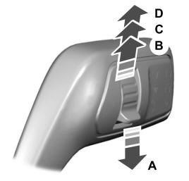
A - Single wipe.