Ford Explorer: Side and Rear Vision / Removal and Installation - Side Obstacle Detection Control Module
Removal
NOTE: LH side shown, RH side is similar.
-
Remove the rear bumper cover.
Refer to: Rear Bumper Cover (501-19 Bumpers, Removal and Installation).
-
NOTE: This step is only necessary if the SODL or SODR is being replaced.
NOTE: If installing a new module, it is necessary to upload the module configuration information to the scan tool prior to removing the module. This information must be downloaded into the new module after installation.
NOTE: If the SODL or SODR did not respond to the diagnostic scan tool, As-Built Data may need to be entered as part of the repair.
Using a diagnostic scan tool, begin the PMI process for the SODL or SODR following the on-screen instructions.
-
Remove the SODL.
-
Disconnect the SODL electrical connector.
-
Remove the SODL screws.
-
Disconnect the SODL electrical connector.
.jpg) |
-
NOTE: The location and number of electrical connectors may vary based on vehicle application.
If required.
Disconnect the SODL wiring harness retainers and position the wiring harness aside.
.jpg) |
-
If required.
Remove the screws and the SODL bracket.
.jpg) |
Installation
-
To install, reverse the removal procedure.
-
Using a diagnostic scan tool, complete the PMI process for the SODL or SODR following the on-screen instructions.
 Diagnosis and Testing - Blind Spot Information System
Diagnostic Trouble Code (DTC) Chart
Diagnostics in this manual assume a certain skill level and knowledge of Ford-specific diagnostic practices. REFER to: Diagnostic Methods (100-00 General Informati..
Other information:
Ford Explorer 2020-2026 Service Manual: Diagnosis and Testing - Horn
Diagnostic Trouble Code (DTC) Chart Diagnostics in this manual assume a certain skill level and knowledge of Ford-specific diagnostic practices. REFER to: Diagnostic Methods (100-00 General Information, Description and Operation). Diagnostic Trouble Code Chart Module DTC Description Action BCM B1323:1..
Ford Explorer 2020-2026 Service Manual: Description and Operation - Module Controlled Functions - Component Location
..
Categories
- Manuals Home
- 6th Generation Explorer Owners Manual
- 6th Generation Explorer Service Manual
- Automatic Transmission - 10-Speed Automatic Transmission – 10R60
- Description and Operation - Jacking and Lifting - Overview
- Interior Trim and Ornamentation
- New on site
- Most important about car
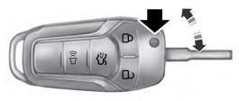
Integrated Keyhead Transmitter (If Equipped)
Use the key blade to start your vehicle and unlock or lock the driver door from outside your vehicle. The integrated keyhead transmitter functions as a programmed ignition key that operates all the locks and starts your vehicle, as well as a remote control.


