Ford Explorer: Battery, Mounting and Cables / Removal and Installation - Generator Current Sensor
Ford Explorer 2020-2026 Service Manual / Electrical / Battery and Charging System / Battery, Mounting and Cables / Removal and Installation - Generator Current Sensor
Removal
NOTE: Removal steps in this procedure may contain installation details.
-
Disconnect the battery/batteries.
Refer to: Battery Disconnect and Connect (414-01 Battery, Mounting and Cables, General Procedures).
-
Release the tabs and remove the BJB cover.
.jpg) |
-
Remove the nut and position the battery cable aside.
Torque: 80 lb.in (9 Nm)
.jpg) |
-
NOTE: The generator current sensor must be installed in the proper position and orientation to function correctly. Note the orientation and position of the generator current sensor tape tab.
Disconnect the generator current sensor electrical connector. Index-mark the battery cable at the generator current sensor. Remove and discard the tape securing the generator current sensor to the battery cable and remove the generator current sensor.
.jpg) |
Installation
-
To install, reverse the removal procedure.
 Removal and Installation - Battery Tray
Removal
NOTE:
Removal steps in this procedure may contain installation details.
Remove the battery.
Refer to: Battery (414-01 Battery, Mounting and Cables, Removal and Installation)...

Other information:
Ford Explorer 2020-2026 Service Manual: General Procedures - Camshaft Surface Inspection
Inspect the camshaft lobes for pitting or damage in the active area. Minor pitting is acceptable outside the active area. The active area includes the opening ramp and closing ramp. The opening ramp is the point where the lifter just begins to lift until the point it reaches the nose of the lobe...
Ford Explorer 2020-2026 Service Manual: Description and Operation - Rear Climate Control - Component Location
..
Categories
- Manuals Home
- 6th Generation Explorer Owners Manual
- 6th Generation Explorer Service Manual
- Description and Operation - Identification Codes
- Description and Operation - Jacking and Lifting - Overview
- Driveline
- New on site
- Most important about car
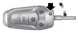
Integrated Keyhead Transmitter (If Equipped)
Use the key blade to start your vehicle and unlock or lock the driver door from outside your vehicle. The integrated keyhead transmitter functions as a programmed ignition key that operates all the locks and starts your vehicle, as well as a remote control.
Copyright © 2026 www.foexplorer.com