Ford Explorer: Fuel Tank and Lines - 2.3L EcoBoost (201kW/273PS) / Removal and Installation - Fuel Tank Filler Pipe
Ford Explorer 2020-2026 Service Manual / Powertrain / Fuel System - General Information / Fuel Tank and Lines - 2.3L EcoBoost (201kW/273PS) / Removal and Installation - Fuel Tank Filler Pipe
Removal
NOTE: Removal steps in this procedure may contain installation steps.
-
Disconnect the battery.
Refer to: Battery Disconnect and Connect (414-01 Battery, Mounting and Cables, General Procedures).
-
With the vehicle in NEUTRAL, position it on a hoist.
Refer to: Jacking and Lifting - Overview (100-02 Jacking and Lifting, Description and Operation).
-
Remove the LHR wheel and tire.
Refer to: Wheel and Tire (204-04A Wheels and Tires, Removal and Installation).
-
-
Remove the nuts.
Torque: 22 lb.in (2.5 Nm)
-
Remove the screws.
Torque: 13 lb.in (1.5 Nm)
-
Remove the bolt.
Torque: 89 lb.in (10 Nm)
-
Remove the LHR wheel liner.
-
Remove the nuts.
.jpg) |
-
Loosen both clamps and remove the hose.
Torque: 28 lb.in (3.2 Nm)
.jpg) |
-
-
Remove the quick release couplings.
Refer to: Quick Release Coupling (310-00A Fuel System - General Information - 2.3L EcoBoost (201kW/273PS), General Procedures).
-
Remove the quick release couplings.
.jpg) |
-
-
Detach the clip and position the drain hose aside.
-
Remove and dicard the bolts.
Torque: 80 lb.in (9 Nm)
-
Detach the clip and position the drain hose aside.
.jpg) |
-
-
Detach the clip.
-
Remove bolts and position aside the brake hose.
Torque: 71 lb.in (8 Nm)
-
Detach the clip.
.jpg) |
-
Remove and Discard the Fuel Filler Door Assembly.
Refer to: Fuel Filler Door Assembly (501-03 Body Closures, Removal and Installation).
-
Remove wheel hub nut.
Refer to: Wheel Bearing and Wheel Hub (204-02 Rear Suspension, Removal and Installation).
-
-
Support the lower control arm using a jack stand.
-
Remove and discard the upper control arm outer bolt and nut.
Torque: 76 lb.ft (103 Nm)
-
Support the lower control arm using a jack stand.
.jpg) |
-
Remove and discard the lower arm vertical link upper
bolt and position aside the knuckle to allow room to remove the fuel
filler pipe.
Torque: 76 lb.ft (103 Nm)
.jpg) |
-
Remove the fuel filler pipe by pulling up on the pipe
through the fuel filler door assembly hole and swinging the bottom of
the fuel filler pipe past the subframe.
.jpg) |
Installation
-
To install, reverse the removal procedure.
 Removal and Installation - Fuel Tank
Special Tool(s) /
General Equipment
Transmission Jack
Removal
NOTE:
Removal steps in this procedure may contain installation steps.
Release the fuel system pressure...

Other information:
Ford Explorer 2020-2026 Service Manual: Removal and Installation - Fuel Tank
Special Tool(s) / General Equipment Transmission Jack Removal NOTE: Removal steps in this procedure may contain installation steps. Release the fuel system pressure. Refer to: Fuel System Pressure Release (310-00A Fuel System - General Information - 2...
Ford Explorer 2020-2026 Service Manual: General Procedures - Welding Precautions
Check WARNING: Invisible ultraviolet and infrared rays emitted in welding can injure unprotected eyes and skin. Always use protection such as a welder's helmet with dark-colored filter lenses of the correct density. Electric welding will produce intense radiation, therefore, filter plate lenses of the deepest shade providing adequate visibility are recommended...
Categories
- Manuals Home
- 6th Generation Explorer Owners Manual
- 6th Generation Explorer Service Manual
- Body and Paint
- Description and Operation - Jacking and Lifting - Overview
- General Procedures - Brake Service Mode Activation and Deactivation
- New on site
- Most important about car
Windshield Wipers
 Push the lever up or down to operate
the windshield wipers.
Push the lever up or down to operate
the windshield wipers.
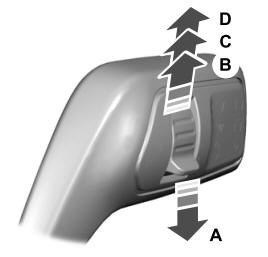
A - Single wipe.
Copyright © 2026 www.foexplorer.com