Ford Explorer: Side Panel Sheet Metal Repairs / Removal and Installation - Front Door Skin Panel
Special Tool(s) /
General Equipment
| Resistance Spotwelding Equipment |
| Scraper for Straight Edges |
| Grinder |
| Hot Air Gun |
| Knife |
| Spot Weld Drill Bit |
| Locking Pliers |
Materials
| Name |
Specification |
Metal Bonding Adhesive
TA-1, TA-1-B, 3M™ 08115, LORD Fusor® 108B |
-
|
Seam Sealer
TA-2-B, 3M™ 08308, LORD Fusor® 805DTM |
-
|
Flexible Foam Repair
3M™ 08463, LORD Fusor® 121 |
-
|
Removal
.jpg) WARNING:
Electric vehicles damaged by a crash may have compromised
high voltage safety systems and present a potential high voltage
electrical shock hazard. Exercise caution and wear appropriate Personal
Protective Equipment (PPE) safety gear, including high voltage safety
gloves and boots. Remove all metallic jewelry, including watches and
rings. Isolate the HV system as directed by the Ford Emergency Response
Guide for the vehicle. Failure to follow these instructions may result
in serious personal injury or death.
WARNING:
Electric vehicles damaged by a crash may have compromised
high voltage safety systems and present a potential high voltage
electrical shock hazard. Exercise caution and wear appropriate Personal
Protective Equipment (PPE) safety gear, including high voltage safety
gloves and boots. Remove all metallic jewelry, including watches and
rings. Isolate the HV system as directed by the Ford Emergency Response
Guide for the vehicle. Failure to follow these instructions may result
in serious personal injury or death.
NOTICE:
BEV (Battery Electric Vehicle), HEV (Hybrid Electric
Vehicle) and PHEV (Plug-In Hybrid Electric Vehicle) contain a
high-voltage battery. Before welding near the high-voltage battery it
must be removed to avoid heat damage.
NOTE:
Left hand (LH) side shown, right hand (RH) side similar.
NOTE:
The door intrusion beam is constructed of boron steel and is
not separately serviced. If bent the intrusion beam may be cold
straightened only. No use of heat is permissible.
-
WARNING:
Before beginning any service procedure in this
manual, refer to health and safety warnings in section 100-00 General
Information. Failure to follow this instruction may result in serious
personal injury.
Refer to: Health and Safety Precautions (100-00 General Information, Description and Operation).
Refer to: High Voltage System Health and Safety Precautions - Overview (100-00 General Information, Description and Operation).
-
Inspect the door for proper alignment. Check upper and
lower door hinges for excessive movement, wear or damage. Install new or
rebuild as necessary.
-
Remove the front door striker.
-
Remove the front door window glass.
Refer to: Front Door Window Glass (501-11 Glass, Frames and Mechanisms, Removal and Installation).
-
Remove the front door exterior mirror.
Refer to: Exterior Mirror (501-09 Rear View Mirrors, Removal and Installation).
-
Remove the front door exterior trim.
Refer to: Front Door Moulding (501-08 Exterior Trim and Ornamentation, Removal and Installation).
-
Remove the front door.
Refer to: Front Door (501-03 Body Closures, Removal and Installation).
-
Remove the exterior door handle.
Refer to: Exterior Front Door Handle (501-14 Handles, Locks, Latches and Entry Systems, Removal and Installation).
-
Remove the weather strip.
-
Remove the seal.
-
Remove the seam sealer.
Use the General Equipment: Hot Air Gun
Use the General Equipment: Scraper for Straight Edges
-
Remove the welds.
Use the General Equipment: Spot Weld Drill Bit
-
Carefully cut through the outer panel only.
Use the General Equipment: Grinder
-
Remove the front door skin panel.
Use the General Equipment: Hot Air Gun
Use the General Equipment: Knife
-
Remove the remaining portion of the door skin panel.
Use the General Equipment: Hot Air Gun
Use the General Equipment: Knife
Installation
WARNING:
Electric vehicles damaged by a crash may have compromised
high voltage safety systems and present a potential high voltage
electrical shock hazard. Exercise caution and wear appropriate Personal
Protective Equipment (PPE) safety gear, including high voltage safety
gloves and boots. Remove all metallic jewelry, including watches and
rings. Isolate the HV system as directed by the Ford Emergency Response
Guide for the vehicle. Failure to follow these instructions may result
in serious personal injury or death.
NOTICE:
BEV (Battery Electric Vehicle), HEV (Hybrid Electric
Vehicle) and PHEV (Plug-In Hybrid Electric Vehicle) contain a
high-voltage battery. Before welding near the high-voltage battery it
must be removed to avoid heat damage.
NOTICE:
The high-voltage battery in a BEV (Battery Electric
Vehicle), HEV (Hybrid Electric Vehicle) or PHEV (Plug-In Hybrid Electric
Vehicle) can be affected and damaged by excessively high temperatures.
The temperature in some body shop paint booths can exceed 60° C (140°
F). Therefore, during refinishing operations, the paint booth
temperature must set at or below 60° C (140° F) with a bake time of 45
minutes or less. Temperatures in excess of 60° C (140° F) or bake
durations longer than 45 minutes will require the high-voltage battery
be removed from the vehicle prior to placing in the paint booth.
NOTICE:
If refinishing cure temperatures exceed 60° C (140° F), the charge port light ring must be removed.
NOTE:
Left hand (LH) side shown, right hand (RH) side similar.
-
WARNING:
Before beginning any service procedure in this
manual, refer to health and safety warnings in section 100-00 General
Information. Failure to follow this instruction may result in serious
personal injury.
Refer to: Health and Safety Precautions (100-00 General Information, Description and Operation).
Refer to: High Voltage System Health and Safety Precautions - Overview (100-00 General Information, Description and Operation).
-
Sand to remove e-coat from the mating surface of the door skin and clean.
-
Install a butyl NVH patch to the back of the door skin panel (obtain locally).
-
Sand to remove all adhesive and foreign materials from the door shell to door skin mating surfaces and clean.
-
NOTE:
Hem closing and panel alignment must be completed before the adhesive has begun to cure.
Apply adhesive.
Material: Metal Bonding Adhesive
/ TA-1, TA-1-B, 3M™ 08115, LORD Fusor® 108B
-
Install the outer door skin panel and lightly clamp.
Using a hammer and dolly or door skin installation tool, partially close
the door hem flange around the perimeter of the door assembly.
Use the General Equipment: Locking Pliers
-
Install the door and check for proper alignment. Adjust as necessary.
-
Install the welds.
Use the General Equipment: Resistance Spotwelding Equipment
-
Remove the door.
-
Using a hammer and dolly or door skin installation tool,
complete the flanging process around the door assembly perimeter.
Smooth any residual adhesive squeeze-out in to the hem flange seam to
act as a sealer.
-
Apply NVH foam.
Material: Flexible Foam Repair
/ 3M™ 08463, LORD Fusor® 121
-
Sand and clean the door hem flange area.
-
Using a Ford approved paint system prime the entire perimeter of the door hem flange.
-
Seam Sealing:
All seams must be sealed to production level.
Material: Seam Sealer
/ TA-2-B, 3M™ 08308, LORD Fusor® 805DTM
-
Refinish the door hem area using a Ford approved paint system.
-
Install the seal.
-
Install the weather strip.
-
Install the door.
Refer to: Front Door (501-03 Body Closures, Removal and Installation).
-
Refinish the repair using a Ford approved paint system and typical refinishing techniques.
-
Restore corrosion protection.
Refer to: Corrosion Prevention (501-25 Body Repairs - General Information, General Procedures).
-
Install the exterior door handle.
Refer to: Exterior Front Door Handle (501-14 Handles, Locks, Latches and Entry Systems, Removal and Installation).
-
Install the front door trim.
Refer to: Front Door Moulding (501-08 Exterior Trim and Ornamentation, Removal and Installation).
-
Install the front door striker.
Torque:
18 lb.ft (25 Nm)
-
Adjust the door.
Refer to: Front Door Alignment (501-03 Body Closures, General Procedures).
-
Install the front door window glass.
Refer to: Front Door Window Glass (501-11 Glass, Frames and Mechanisms, Removal and Installation).
-
Install the exterior mirror.
Refer to: Exterior Mirror (501-09 Rear View Mirrors, Removal and Installation).
Special Tool(s) /
General Equipment
Resistance Spotwelding Equipment
Spherical Cutter
Plasma Cutter
Hot Air Gun
Air Body Saw
8 mm Drill Bit
MIG/MAG Welding Equipment..
Special Tool(s) /
General Equipment
Resistance Spotwelding Equipment
Scraper for Straight Edges
Grinder
Hot Air Gun
Knife
Spot Weld Drill Bit
Locking Pliers
Mater..
Other information:
Special Tool(s) /
General Equipment
Interior Trim Remover
Removal
NOTE:
Driver seat shown, passenger seat similar.
Remove the front seat.
Refer to: Front Seat (501-10A Front Seats, Removal and Installation).
Release the front seat backrest panel straps...
Diagnostic Trouble Code (DTC) Chart
Diagnostics in this manual assume a certain skill level and knowledge of Ford-specific diagnostic practices. REFER to: Diagnostic Methods (100-00 General Information, Description and Operation).
REFER to: Battery (414-01 Battery, Mounting and Cables, Diagnosis and Testing)...
.jpg)
.jpg)
.jpg)
.jpg)
.jpg)
.jpg)
.jpg)
.jpg)
.jpg)
.jpg)
.jpg)
.jpg)
.jpg)
.jpg)
.jpg)
.jpg)
.jpg)
.jpg)
.jpg)
.jpg)
.jpg)
 Removal and Installation - B-Pillar Outer Panel
 Removal and Installation - Rear Door Skin Panel
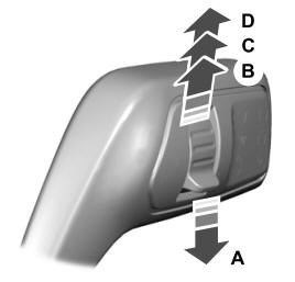
 Push the lever up or down to operate
the windshield wipers.
Push the lever up or down to operate
the windshield wipers.