Ford Explorer: Front End Body Panels / Removal and Installation - Engine Rear Undershield
Ford Explorer 2020-2026 Service Manual / Body and Paint / Body and Paint / Front End Body Panels / Removal and Installation - Engine Rear Undershield
Removal
NOTE: Removal steps in this procedure may contain installation details.
-
Remove the Engine front undershield.
Refer to: Engine Front Undershield (501-02 Front End Body Panels, Removal and Installation).
-
Remove the bolts
Torque: 22 lb.in (2.5 Nm)
.jpg) |
-
-
Remove the retainers
-
Remove the push pins and the engine rear undershield
-
Remove the retainers
.jpg) |
-
If equipped.
Remove the bolts and the engine rear undershield.
Torque: 18 lb.ft (25 Nm)
.jpg) |
-
If equipped.
Remove the bolts and the engine rear undershield.
Torque: 18 lb.ft (25 Nm)
.jpg) |
Installation
-
To install, reverse the removal procedure.
 Removal and Installation - Engine Front Undershield
Removal
NOTE:
Removal steps in this procedure may contain installation details.
With the vehicle in NEUTRAL, position it on a hoist.
Refer to: Jacking and Lifting (100-02 Jacking and Li..
 Removal and Installation - Fender
Special Tool(s) /
General Equipment
Knife
Materials
Name
Specification
Flexible Foam Repair3M™ 08463, LORD Fusor® 121
-
Removal
NOTE:
Removal steps in this pro..
Other information:
Ford Explorer 2020-2026 Service Manual: Removal and Installation - Selector Shaft Seal
Special Tool(s) / General Equipment 307-549Installer, Shift Shaft Fluid SealTKIT-2005D1-F1 Materials Name Specification Motorcraft® MERCON® ULV Automatic Transmission FluidXT-12-QULV WSS-M2C949-A, MERCON® ULV Removal With the vehicle in NEUTRAL, position it on a hoist...
Ford Explorer 2020-2026 Service Manual: Description and Operation - Rear Climate Control - System Operation and Component Description
System Operation System Diagram Item Description 1 IPC 2 GWM 3 HVAC control module 4 Rear air distribution door actuator 5 Rear temperature door actuator 6 Rear blower motor relay 7 Rear blower motor speed control 8 Rear blower motor 9 RHVAC control module Network Message Charts Mo..
Categories
- Manuals Home
- 6th Generation Explorer Owners Manual
- 6th Generation Explorer Service Manual
- Description and Operation - Jacking and Lifting - Overview
- Fuel Filler Funnel Location & Running Out of Fuel
- General Procedures - Rear Camber Adjustment
- New on site
- Most important about car
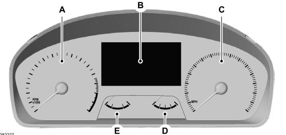
Gauges
4 Inch Display

A - Tachometer.
B - Information display.
C - Speedometer.
D - Fuel gauge.
E - Engine coolant temperature gauge.
Copyright © 2026 www.foexplorer.com
