Ford Explorer: Engine - 2.3L EcoBoost (201kW/273PS) / Removal and Installation - Crankshaft Pulley
Special Tool(s) / General Equipment
.jpg) |
303-1521 Alignment Tool, Crankshaft Position Sensor TKIT-2010C-FLM |
.jpg) |
303-1686 Holding Tool, Camshaft |
.jpg) |
303-1689 Holding Tool, Crank Damper |
 |
303-507 Timing Peg, Crankshaft TDC TKIT-2001N-FLM TKIT-2001N-ROW |
Materials
| Name | Specification |
|---|---|
| Motorcraft® Silicone Brake Caliper Grease and Dielectric Compound XG-3-A |
ESE-M1C171-A |
Removal
NOTICE: Do not loosen or remove the crankshaft pulley bolt without first installing the special tools as instructed in this procedure. The crankshaft pulley and the crankshaft timing sprocket are not keyed to the crankshaft. The crankshaft, the crankshaft sprocket and the pulley are fitted together by friction. For that reason, the crankshaft sprocket is also unfastened if the pulley bolt is loosened. Before any repair requiring loosening or removal of the crankshaft pulley bolt, the crankshaft and camshafts must be locked in place by the special service tools, otherwise severe engine damage can occur.
NOTICE: During engine repair procedures, cleanliness is extremely important. All parts must be thoroughly cleaned and any foreign material, including any material created while cleaning gasket surfaces, that enters the oil passages, coolant passages or the oil pan, can cause engine failure.
-
With the vehicle in NEUTRAL, position it on a hoist.
Refer to: Jacking and Lifting - Overview (100-02 Jacking and Lifting, Description and Operation).
-
Remove the bolts and the suspension support bar.
.jpg) |
-
NOTICE: Do not pull the engine appearance cover forward or sideways to remove. Failure to press straight upward on the underside of the cover at the attachment points may result in damage to the cover or engine components.
-
Remove the engine appearance cover nuts.
-
Place your hand under the engine appearance cover at
the grommet location and push straight up to release the grommet from
the stud.
-
After the grommet has been released from the stud, remove the appearance cover from the engine.
-
Remove the engine appearance cover nuts.
.jpg) |
-
Remove the following items:
-
Remove the cowl panel.
Refer to: Cowl Panel (501-02 Front End Body Panels, Removal and Installation).
-
Remove the air cleaner.
Refer to: Air Cleaner (303-12A Intake Air Distribution and Filtering - 2.3L EcoBoost (201kW/273PS), Removal and Installation).
-
Remove the accessory drive belt.
Refer to: Accessory Drive Belt (303-05A Accessory Drive - 2.3L EcoBoost (201kW/273PS), Removal and Installation).
-
Remove the cowl panel.
-
Remove the air cleaner inlet tube.
.jpg) |
-
-
Detach the EVAP canister tube retainer.
-
Detach the coolant hose and wiring harness retainers.
-
Remove the bolts and the air cleaner bracket.
-
Detach the EVAP canister tube retainer.
.jpg) |
-
-
Remove pin-type retainer.
-
Remove the bolts and the underbody shield.
-
Remove pin-type retainer.
.jpg) |
-
-
Disconnect the CKP sensor electrical connector.
-
Remove the bolts and the CKP sensor.
-
Disconnect the CKP sensor electrical connector.
.jpg) |
-
Turn the crankshaft clockwise until the No.1 piston is 45 degrees BTDC using the guide holes on the engine front cover and the crankshaft pulley.
.jpg) |
-
Remove the engine plug bolt.
.jpg) |
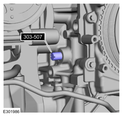
- Install Special Service Tool: 303-507 Timing Peg, Crankshaft TDC.
 |
-
NOTE: The Crankshaft TDC Timing Peg will contact the crankshaft and prevent it from turning past TDC. However, the crankshaft can still be rotated in the counterclockwise direction. The crankshaft must remain at the TDC position during the crankshaft pulley removal and installation.
NOTE: The engine front cover is removed from graphic for clarity.
Rotate the crankshaft clockwise until the contacts the special tool.
Use Special Service Tool: 303-507 Timing Peg, Crankshaft TDC.
.jpg) |
-
Remove the RH and LH CMP sensors.
Refer to: Camshaft Position (CMP) Sensor (303-14A Electronic Engine Controls - 2.3L EcoBoost (201kW/273PS), Removal and Installation).
-
NOTE: Exhaust camshaft shown, intake camshaft similar.
NOTE: The camshaft trigger wheels are offset. If the camshaft trigger wheels are not correctly aligned, the camshaft holding tools will not be able to be installed in the next step.
Make sure the camshaft trigger wheels are correctly aligned as shown. If the trigger wheels are not correctly aligned, remove the TDC Timing Peg and rotate the crankshaft three-fourths of a revolution clockwise and repeat steps 11 and 12 of this removal procedure.
.jpg) |
-
NOTE: Removing the O-ring seals will aid in the installation of 303-1686.
Remove the O-ring seals from 303-1686.
Use Special Service Tool: 303-1686 Holding Tool, Camshaft.
.jpg) |
-
NOTICE: The Camshaft Alignment Tool is for camshaft alignment only. Using this tool to prevent engine rotation can result in engine damage.
NOTICE: Do not force the camshaft holding tool into the valve cover or damage can result to the camshaft trigger wheels.
NOTE: The camshaft trigger wheels are offset. If the Camshaft Holding Tools cannot be installed, remove the TDC Timing Peg and rotate the crankshaft three-fourths of a revolution clockwise and repeat steps 10 and 11 of this removal procedure.
Install Special Service Tool: 303-1686 Holding Tool, Camshaft.
.jpg) |
-
NOTICE: The crankshaft must remain in the TDC position during removal of the pulley bolt or damage to the engine can occur. Therefore, the crankshaft pulley must be held in place with the Crank Damper Holding Tool and the bolt should be removed using an air impact wrench (1/2-in drive minimum).
-
Using the special tool, remove the bolt, washer and the crankshaft pulley.
Use Special Service Tool: 303-1689 Holding Tool, Crank Damper.
-
NOTE: If necessary, retain the original crankshaft pulley bolt to use for the removal of the crankshaft front seal.
Discard the bolt.
-
Using the special tool, remove the bolt, washer and the crankshaft pulley.
.jpg) |
Installation
-
Lubricate the crankshaft pulley with clean engine oil.
.jpg) |
-
Position the crankshaft pulley onto the crankshaft with the access hole at the 6 o'clock position.
.jpg) |
-
NOTE: This step will correctly align the crankshaft pulley to the crankshaft.
Install an M6 bolt finger tight.
.jpg) |
-
NOTICE: The crankshaft must remain in the TDC position during installation of the pulley bolt or damage to the engine can occur. Therefore, the crankshaft pulley must be held in place with the Crank Damper Holding Tool and the bolt should be installed using hand tools only.
With the aid of an assistant and using the special tool, install the new crankshaft bolt and washer and tighten.
Use Special Service Tool: 303-1689 Holding Tool, Crank Damper.
Torque:
Stage 1: 74 lb.ft (100 Nm)
Stage 2: 90°
.jpg) |
-
Remove the M6 bolt.
.jpg) |
-
NOTE: Do not tighten the CKP sensor bolts at this time.
Install the CKP sensor and the bolts finger tight.
.jpg) |
-
Install the special tool onto the CKP sensor and the tooth of the crankshaft pulley trigger wheel and tighten the bolts.
Use Special Service Tool: 303-1521 Alignment Tool, Crankshaft Position Sensor.
Torque: 97 lb.in (11 Nm)
.jpg) |
- Remove Special Service Tool: 303-1521 Alignment Tool, Crankshaft Position Sensor.
.jpg) |
-
Connect the CKP sensor electrical connector.
.jpg) |
-
NOTICE: Do not rotate the crankshaft until the special tools 303-1686 are removed from the valve cover.
Remove Special Service Tool: 303-507 Timing Peg, Crankshaft TDC.
.jpg) |
-
Install the engine plug bolt.
Torque: 177 lb.in (20 Nm)
.jpg) |
- Remove Special Service Tool: 303-1686 Holding Tool, Camshaft.
|
-
Install the O-ring seals on 303-1686.
|
-
Install the RH and LH CMP sensors.
Refer to: Camshaft Position (CMP) Sensor (303-14A Electronic Engine Controls - 2.3L EcoBoost (201kW/273PS), Removal and Installation).
-
-
Install the underbody shield and the bolts.
Torque: 22 lb.in (2.5 Nm)
-
Install pin-type retainer.
-
Install the underbody shield and the bolts.
|
-
-
Install the air cleaner bracket and the bolts.
Torque: 59 lb.ft (80 Nm)
-
Attach the coolant hose and wiring harness retainers.
-
Attach the EVAP canister tube retainer.
-
Install the air cleaner bracket and the bolts.
|
-
Install the air cleaner inlet tube.
|
-
Install the following items:
-
Install the accessory drive belt.
Refer to: Accessory Drive Belt (303-05A Accessory Drive - 2.3L EcoBoost (201kW/273PS), Removal and Installation).
-
Install the air cleaner.
Refer to: Air Cleaner (303-12A Intake Air Distribution and Filtering - 2.3L EcoBoost (201kW/273PS), Removal and Installation).
-
Install the cowl panel.
Refer to: Cowl Panel (501-02 Front End Body Panels, Removal and Installation).
-
Install the accessory drive belt.
-
-
NOTE: Lubricating the grommets with silicone grease will aid in the installation of the engine appearance cover, and any future removal and installation of the cover.
Lubricate each grommet with silicone grease.
Material: Motorcraft® Silicone Brake Caliper Grease and Dielectric Compound / XG-3-A (ESE-M1C171-A)
-
Position the engine appearance cover onto engine with the grommet aligned with the stud.
-
Press down on the engine appearance cover at the
grommet location to attach the grommet onto the stud and install the
nuts.
Torque: 44 lb.in (5 Nm)
-
.jpg) |
-
Install the suspension support bar and the bolts.
Torque: 22 lb.ft (30 Nm)
|
-
Use the Powertrain Control Module (PCM) Misfire Monitor Profile Correction routine in the diagnostic scan tool.
 Removal and Installation - Crankshaft Front Seal
Special Tool(s) /
General Equipment
303-096
(T74P-6150-A)
Installer, Camshaft Front Oil SealTKIT-2009TC-F
303-409
(T92C-6700-CH)
Remover, Crankshaft SealTKIT-1992-FH/FMH/FLMHTKIT-199..
 Removal and Installation - Crankshaft Rear Seal
Special Tool(s) /
General Equipment
303-328
(T88P-6701-B1)
Replacer, Rear SealTKIT-1988-FLMTKIT-1988-FTKIT-1988-LM
Oil Drain Equipment
Materials
Name
Specification
Motorcraf..
Other information:
Ford Explorer 2020-2026 Owners Manual: Principle of Operation
WARNING: The system is designed to aid the driver. It is not intended to replace your attention and judgment. You are still responsible to drive with due care and attention. WARNING: At all times, you are responsible for controlling your vehicle, supervising the system and intervening, if required...
Ford Explorer 2020-2026 Service Manual: Removal and Installation - Air Distribution Door Actuator
Removal Remove the glove compartment. Refer to: Glove Compartment (501-12 Instrument Panel and Console, Removal and Installation). Remove the screws and the air distribution door actuator. Disconnect the electrical connector...
Categories
- Manuals Home
- 6th Generation Explorer Owners Manual
- 6th Generation Explorer Service Manual
- Body and Paint
- Electric Parking Brake
- Auxiliary Power Points
- New on site
- Most important about car
Fastening the Seatbelts
The front outboard and rear safety restraints in the vehicle are combination lap and shoulder belts.
