Ford Explorer: Engine System - General Information / General Procedures - Valve Guide Inner Diameter
Ford Explorer 2020-2026 Service Manual / Powertrain / Engine / Engine System - General Information / General Procedures - Valve Guide Inner Diameter
Check
NOTE: Refer to the appropriate Section 303-01 for the specification.
-
NOTE: Valve guides tend to wear in an hourglass pattern. The ball gauge can be inserted into the combustion chamber side of the valve guide, if necessary.
-
Use a ball gauge to determine the inside diameter of
the valve guides in 2 directions at the top, middle and bottom of the
valve guide.
-
Measure the ball gauge with a micrometer.
-
If the valve guide is not within specifications, install a new cylinder head assembly.
-
Use a ball gauge to determine the inside diameter of
the valve guides in 2 directions at the top, middle and bottom of the
valve guide.
.jpg) |
 General Procedures - Spark Plug Inspection
Inspection
NOTE:
Dropped spark plugs should always be discarded.
Unfired
An unfired spark plug should appear very clean
with a pure nickel finish to the threads and ground strap..
 General Procedures - Valve Stem Diameter
Check
NOTE:
Refer to the appropriate Section 303-01 for the specification.
Measure the diameter of each intake and exhaust valve
stem at the points shown...
Other information:
Ford Explorer 2020-2026 Owners Manual: Personal Safety System™
This system provides an improved overall level of frontal crash protection to front seat occupants and is designed to help further reduce the risk of airbag-related injuries. The system analyzes different occupant conditions and crash severity before activating the appropriate safety devices to help better protect occupants in a variety of frontal crash situations...
Ford Explorer 2020-2026 Service Manual: Removal and Installation - Rear Heater Core Outlet Line
Removal NOTE: The rear heater core outline is installed from the factory as a one-piece assembly. The replacement part is supplied as an assembly, containing the rear heater core inlet line and the rear evaporator inlet and outlet lines. Remove the rear evaporator rear outlet and inlet line...
Categories
- Manuals Home
- 6th Generation Explorer Owners Manual
- 6th Generation Explorer Service Manual
- Using Tether Straps
- General Procedures - Brake Service Mode Activation and Deactivation
- Engine - 2.3L EcoBoost (201kW/273PS)
- New on site
- Most important about car
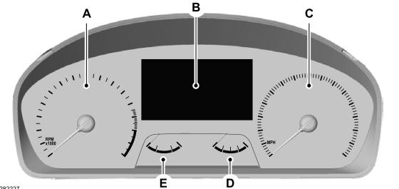
Gauges
4 Inch Display

A - Tachometer.
B - Information display.
C - Speedometer.
D - Fuel gauge.
E - Engine coolant temperature gauge.
Copyright © 2026 www.foexplorer.com
