Ford Explorer: Supplemental Restraint System / General Procedures - Inspection and Repair after a Supplemental Restraint System (SRS) Deployment
Inspection
NOTE: Deployable devices such as airbags, pretensioners and inflatable belt inflators, may deploy alone or in various combinations depending on the impact event.
NOTE: Always refer to the appropriate workshop manual procedures prior to carrying out vehicle repairs affecting the SRS and seatbelt system.
NOTE: The SRS must be fully operational and free of faults before releasing the vehicle to the customer.
-
NOTE: Refer to the correct removal and installation procedure for all SRS components being installed.
When any deployable device or combination of devices have deployed and/or the RCM has DTC B1193:00 (event threshold exceeded) in memory, the repair of the vehicle SRS is to include the removal of all deployed devices and the installation of new deployable devices, the removal of all impact sensors and installation of new impact sensors and the removal and installation of a new RCM. Diagnostic Trouble Codes (DTCs) must be cleared from all required modules after repairs are carried out.
-
NOTE: After installation of new OCS components, use a diagnostic scan tool to carry out the OCS Reset procedure as instructed in the workshop manual.
When a vehicle has been involved in a collision and the OCSM has DTC B1193:00 stored in memory, inspect the OCS for damage and repair as necessary. If installation of an OCS component is required, an OCS service kit must be installed.
-
When any damage to the impact sensor mounting points or
mounting hardware has occurred, repair or install new mounting points
and mounting hardware as needed.
-
When the driver airbag has deployed, install a new steering wheel and clockspring.
-
NOTICE: Precise tolerances are required when manufacturing a steering column. Never install a repaired, rebuilt or remanufactured steering column, always install a new steering column. Failure to follow this direction can result in steering column failure.
Install a new adaptive energy absorption steering column if:
-
Steering wheel is bent, loose or damaged
-
Steering column functionality is binding, bent or sticking
-
Steering column bearings brinelling or damaged
-
Steering shaft bent, loose or damaged
-
Any abnormal steering column movement
-
Steering wheel is bent, loose or damaged
-
New driver and/or front passenger seatbelt systems
(including seatbelt retractors, seatbelt buckles and height adjusters)
must be installed if the vehicle is involved in a collision that results
in deployment of the driver and/or front passenger seatbelt
pretensioners.
-
New second row seatbelt systems (including seatbelt
retractors, seatbelt buckles and inflators) must be installed if the
vehicle is involved in a collision that results in deployment of the
rear seatbelt pretensioners (if equipped) or inflatable seatbelt system
(if equipped).
-
Inspect the entire vehicle for damage, including the following components:
-
Instrument panel and mounting points
-
Instrument panel braces and brackets
-
Instrument panel knee bolsters and mounting points
-
Safety Canopy® and mounting points
-
Seatbelts, seatbelt buckles, seatbelt retractors and seatbelt anchors.
-
Seats and seat mounting points
-
SRS wiring, wiring harnesses and connectors
-
Instrument panel and mounting points
-
After carrying out the review and inspection of the
entire vehicle for damage, repair or install new components as needed.
-
Inspect the fuel system for damage or leaks. Repair the system and install new components as necessary.
-
-
Connect a diagnostic scan tool and view the BCM CRASH PID.
-
If the BCM CRASH PID is present and reads 'Yes', use the diagnostic scan tool to carry out the BCM Crash Status Reset under "Electrical - Service Functions".
-
If the BCM CRASH PID reads 'No' or is not present, complete any necessary repairs before returning the vehicle to the customer.
-
Connect a diagnostic scan tool and view the BCM CRASH PID.
 General Procedures - Clockspring Adjustment
Special Tool(s) /
General Equipment
Adhesive Tape
WARNING:
If the clockspring is not correctly centralized, it may fail
prematurely...
 General Procedures - Pyrotechnic Device Disposal
Disposal
Disposal of Deployable Devices and Pyrotechnic Devices That Are Undeployed-Inoperative
NOTE:
All inoperative airbags, seatbelt pretensioners and
inflatable seatbelt inflators have ..
Other information:
Ford Explorer 2020-2025 Service Manual: Removal and Installation - Crankcase Vent Oil Separator
Removal NOTE: Removal steps in this procedure may contain installation details. Remove the intake manifold. Refer to: Intake Manifold (303-01A) . Disconnect the quick release coupling and remove the hose. Refer to: Quick Release Coupling (310-00A Fuel System - General Information - 2...
Ford Explorer 2020-2025 Service Manual: Description and Operation - Exterior Lighting - System Operation and Component Description
System Operation Headlamps System Diagram Item Description 1 HS-CAN2 2 BCM 3 LH low beam 4 RH low beam 5 SCCM 6 LH steering column multifunction switch 7 IPMA 8 GWM 9 HS-CAN1 10 Start/Stop switch 11 HCM 12 LIN 13 LIN 14 PCM 15 LH headlamp..
Categories
- Manuals Home
- 6th Generation Explorer Owners Manual
- 6th Generation Explorer Service Manual
- Interior Trim and Ornamentation
- Fuel Filler Funnel Location & Running Out of Fuel
- Removal and Installation - Liftgate Trim Panel
- New on site
- Most important about car
Child Safety Locks
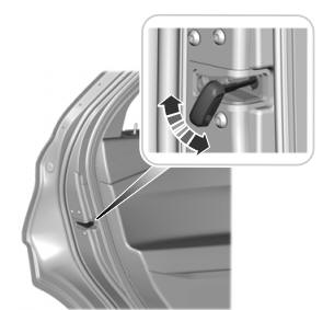
When these locks are set, you cannot open the rear doors from the inside.

A child safety lock is on the rear edge of each rear door. You must set the child safety lock separately on each door.
Left-Hand Side
