Ford Explorer: Perimeter Anti-Theft Alarm / Diagnosis and Testing - Perimeter Anti-Theft Alarm

Ford Explorer 2020-2024 Service Manual / Electrical / Electronic Feature Group / Perimeter Anti-Theft Alarm / Diagnosis and Testing - Perimeter Anti-Theft Alarm

Diagnostic Trouble Code (DTC) Chart

Diagnostics in this manual assume a certain skill level and knowledge of Ford-specific diagnostic practices.
REFER to: Diagnostic Methods (100-00 General Information, Description and Operation).


  Diagnostic Trouble Code Chart


Module   DTC Description Action
  BCM B1305:01 Hood Switch: General Electrical Failure   GO to Pinpoint Test C
  BCM B1305:11 Hood Switch: Circuit Short To Ground   GO to Pinpoint Test A
  BCM B1305:15 Hood Switch: Circuit Short To Battery or Open   GO to Pinpoint Test C

Symptom Chart: Anti-Theft - Perimeter

Diagnostics in this manual assume a certain skill level and knowledge of Ford-specific diagnostic practices.
REFER to: Diagnostic Methods (100-00 General Information, Description and Operation).

Condition Possible Sources Actions
No horn output during alarm activation Horn output concern DIAGNOSE the inoperative horn
REFER to: Horn (413-06 Horn, Diagnosis and Testing).
The alarm system does not activate from an unauthorized entry at a door Door ajar concern DIAGNOSE the courtesy lamps not illuminating with a door open
REFER to: Interior Lighting (417-02 Interior Lighting, Diagnosis and Testing).
The alarm system does not activate from an unauthorized entry at the liftgate Door ajar concern DIAGNOSE the courtesy lamps not illuminating with a door open
REFER to: Interior Lighting (417-02 Interior Lighting, Diagnosis and Testing).
The alarm system does not activate from an unauthorized entry at the hood Refer to the Pinpoint Test   GO to Pinpoint Test A
The alarm system does not arm or no turn signals flash confirmation Refer to the Pinpoint Test   GO to Pinpoint Test B
The alarm system falsely activates
  • A valid PATS key read was NOT received when the ignition transitioned to RUN
  • Panic button pressed on a RKE transmitter
  • Door ajar input
  • Hood ajar input
  • An intermittent fault exists. Using a diagnostic scan tool, view the following BCM Parameter Identifications (PIDs) to identify and isolate the cause of the last alarm activation.
    • Most Recent Alarm Trigger Event (ALARM_EVT_1)
    • 2nd Most Recent Alarm Trigger Event (ALARM_EVT_2)
    • 3rd Most Recent Alarm Trigger Event (ALARM_EVT_3)
    • 4th Most Recent Alarm Trigger Event (ALARM_EVT_4)
  • For a PID value of "Panic" causing the false alarm event, the system is operating correctly at this time. INSTRUCT the customer in the correct operation of the panic alarm feature. REFER to "Panic Alarm" in the Owner's Literature.
  • For a PID value of "Door Ajar" causing the false alarm event, DIAGNOSE the ajar switches.
    REFER to: Interior Lighting (417-02 Interior Lighting, Diagnosis and Testing).
  • For a PID value of "Hood Ajar" causing the false alarm event, diagnose the hood ajar switch. GO to Pinpoint Test C

Pinpoint Tests


PINPOINT TEST A : THE ALARM SYSTEM DOES NOT ACTIVATE FROM AN UNAUTHORIZED ENTRY AT THE HOOD

Refer to Wiring Diagrams Cell 117 for schematic and connector information.

Normal Operation and Fault Conditions

REFER to: Perimeter Anti-Theft Alarm - System Operation and Component Description (419-01A Perimeter Anti-Theft Alarm, Description and Operation).

DTC Fault Trigger Conditions

DTC Description Fault Trigger Condition
BCM B1305:11 Hood Switch: Circuit Short To Ground Sets when the BCM detects a short to ground from the hood ajar switch input during a self-test.

Possible Sources

  • Wiring, terminals or connectors
  • Hood latch
  • BCM

Visual Inspection and Pre-checks

  • Inspect the hood latch for damage.
A1 MONITOR THE BCM (BODY CONTROL MODULE) HOOD AJAR SWITCH (HOOD_SW) PID (PARAMETER IDENTIFICATION)
  • Ignition ON.
  • Using a diagnostic scan tool, view the BCM Parameter Identifications (PIDs).
  • Using a diagnostic scan tool, monitor the BCM HOOD_SW PID.
  • Disconnect: Hood Ajar Switch C127.

Does the PID read AJAR when the switch is disconnected?
Yes INSTALL a new hood latch.
REFER to: Hood Latch (501-14 Handles, Locks, Latches and Entry Systems, Removal and Installation).
No GO to A2

A2 CHECK THE HOOD AJAR SWITCH INPUT CIRCUIT FOR A SHORT TO GROUND
  • Ignition OFF.
  • Disconnect: BCM C2280F.
  • Measure:
    Click to display connectors
    Positive Lead Measurement / Action Negative Lead
      C127-2   Ground

Is the resistance greater than 10,000 ohms?
Yes GO to A3
No REPAIR the circuit.

A3 CHECK FOR CORRECT BCM (BODY CONTROL MODULE) OPERATION
  • Disconnect and inspect all BCM connectors.
  • Repair:
    • corrosion (install new connector or terminals – clean module pins)
    • damaged or bent pins – install new terminals/pins
    • pushed-out pins – install new pins as necessary
  • Reconnect all BCM connectors. Make sure they seat and latch correctly.
  • Operate the system and determine if the concern is still present.

Is the concern still present?
Yes CHECK OASIS for any applicable service articles: TSB, GSB, SSM, or FSA. If a service article exists for this concern, DISCONTINUE this test and FOLLOW the service article instructions. If no service articles address this concern, INSTALL a new BCM.
REFER to: Body Control Module (BCM) (419-10 Multifunction Electronic Modules, Removal and Installation).
.
No The system is operating correctly at this time. The concern may have been caused by module connections. ADDRESS the root cause of any connector or pin issues.

PINPOINT TEST B : THE ALARM SYSTEM DOES NOT ARM OR NO TURN SIGNALS FLASH CONFIRMATION

Refer to Wiring Diagrams Cell 95 for schematic and connector information.

Normal Operation and Fault Conditions

REFER to: Perimeter Anti-Theft Alarm - System Operation and Component Description (419-01A Perimeter Anti-Theft Alarm, Description and Operation).

Possible Sources

  • Door ajar switch input
  • Hood ajar switch input
  • Liftgate ajar switch output
  • Turn signal output
  • RKE transmitter concern
  • BCM
NOTICE: Use the correct probe adapter(s) when making measurements. Failure to use the correct probe adapter(s) may damage the connector.
B1 CHECK FOR BCM (BODY CONTROL MODULE) DTC (DIAGNOSTIC TROUBLE CODE)

NOTE: DTC B1305:01 or B1305:15 sets if the hood is open. Make sure the hood is closed prior to running the self-test.

  • Ignition ON.
  • Using a diagnostic scan tool, perform the BCM self-test.

Is DTC B1305:01 or B1305:15 present?
Yes GO to Pinpoint Test C
No GO to B2

B2 CHECK THE DOOR AND LIFTGATE AJAR SWITCH INPUTS
  • Close all the doors and liftgate.
  • Observe the IPC.

Does the IPC indicate a door or the liftgate is ajar?
Yes
REFER to: Instrumentation, Message Center and Warning Chimes (413-01 Instrumentation, Message Center and Warning Chimes, Diagnosis and Testing).
No GO to B3

B3 VERIFY THE HAZARD FLASHER LAMP OPERATION
  • Ignition OFF.
  • Activate the hazard flasher lamp function and observe the turn signals.

Do all the turn signals flash on and off?
Yes GO to B4
No DIAGNOSE the inoperative turn signals.
REFER to: Turn Signal and Hazard Lamps (417-01 Exterior Lighting, Diagnosis and Testing).

B4 CHECK THE RKE (REMOTE KEYLESS ENTRY) TRANSMITTER FUNCTION
  • Using the RKE transmitter, lock and unlock the doors.

Do the doors lock and unlock?
Yes GO to B5
No DIAGNOSE the inoperative RKE transmitter.
REFER to: Locks, Latches and Entry Systems (501-14 Handles, Locks, Latches and Entry Systems, Diagnosis and Testing).

B5 CHECK FOR CORRECT BCM (BODY CONTROL MODULE) OPERATION
  • Disconnect and inspect all the BCM connectors.
  • Repair:
    • corrosion (install new connector or terminals – clean module pins)
    • damaged or bent pins – install new terminals/pins
    • pushed-out pins – install new pins as necessary
  • Reconnect the BCM connectors. Make sure they seat and latch correctly.
  • Operate the system and determine if the concern is still present.

Is the concern still present?
Yes CHECK OASIS for any applicable service articles: TSB, GSB, SSM, or FSA. If a service article exists for this concern, DISCONTINUE this test and FOLLOW the service article instructions. If no service articles address this concern, INSTALL a new BCM.
REFER to: Body Control Module (BCM) (419-10 Multifunction Electronic Modules, Removal and Installation).
.
No The system is operating correctly at this time. The concern may have been caused by module connections. ADDRESS the root cause of any connector or pin issues.

PINPOINT TEST C : B1305:01, B1305:15

Refer to Wiring Diagrams Cell 117 for schematic and connector information.

Normal Operation and Fault Conditions

REFER to: Perimeter Anti-Theft Alarm - System Operation and Component Description (419-01A Perimeter Anti-Theft Alarm, Description and Operation).

DTC Fault Trigger Conditions

DTC Description Fault Trigger Condition
BCM B1305:01 Hood Switch: General Electrical Failure Sets when the BCM detects an open from the hood ajar switch input during a self-test. This DTC also sets if the self-test is carried out with the hood open.
BCM B1305:15 Hood Switch: Circuit Short To Battery Or Open Sets when the BCM detects a short to battery or open from the hood ajar switch input during a self-test.

Possible Sources

  • Wiring, terminals or connectors
  • Hood latch
  • BCM

Visual Inspection and Pre-checks

  • Inspect the hood latch for damage.
NOTICE: Use the correct probe adapter(s) when making measurements. Failure to use the correct probe adapter(s) may damage the connector.
C1 CHECK THE HOOD AJAR SWITCH
  • Disconnect: Hood Ajar Switch C127.
  • Ignition ON.
  • Connect:
    Click to display connectors
    Positive Lead Measurement / Action Negative Lead
      C127-2   C127-1
  • Using a diagnostic scan tool, perform the BCM self-test.

Is DTC B1305:01 or B1305:15 still present?
Yes REMOVE the fused jumper wire. GO to C2
No REMOVE the fused jumper wire. INSTALL a new hood latch.
REFER to: Hood Latch (501-14 Handles, Locks, Latches and Entry Systems, Removal and Installation).

C2 CHECK THE HOOD AJAR SWITCH GROUND CIRCUIT FOR AN OPEN
  • Connect a fused jumper wire:
    Click to display connectors
    Positive Lead Measurement / Action Negative Lead
      C127-2   Ground
  • Using a diagnostic scan tool, perform the BCM self-test.

Is DTC B1305:01 still present?
Yes REMOVE the fused jumper wire. GO to C3
No REMOVE the fused jumper wire. REPAIR the circuit.

C3 CHECK THE HOOD AJAR SWITCH INPUT CIRCUIT FOR AN OPEN
  • Ignition OFF.
  • Disconnect: BCM C2280F.
  • Measure:
    Click to display connectors
    Positive Lead Measurement / Action Negative Lead
      C127-2   C2280F-14

Is the resistance less than 3 ohms?
Yes GO to C4
No REPAIR the circuit.

C4 CHECK FOR CORRECT BCM (BODY CONTROL MODULE) OPERATION
  • Disconnect and inspect all the BCM connectors.
  • Repair:
    • corrosion (install new connector or terminals – clean module pins)
    • damaged or bent pins – install new terminals/pins
    • pushed-out pins – install new pins as necessary
  • Reconnect the BCM connectors. Make sure they seat and latch correctly.
  • Operate the system and determine if the concern is still present.

Is the concern still present?
Yes CHECK OASIS for any applicable service articles: TSB, GSB, SSM, or FSA. If a service article exists for this concern, DISCONTINUE this test and FOLLOW the service article instructions. If no service articles address this concern, INSTALL a new BCM.
REFER to: Body Control Module (BCM) (419-10 Multifunction Electronic Modules, Removal and Installation).
.
No The system is operating correctly at this time. The concern may have been caused by module connections. ADDRESS the root cause of any connector or pin issues.


    Description and Operation - Perimeter Anti-Theft Alarm - System Operation and Component Description

    System Operation System Diagram Item Description 1 Power Liftgate 2 Hood Ajar Switch 3 Passive Key 4 with Push Button Start 5 Horn 6 GWM ..

    Passive Anti-Theft System (PATS)

    ..

    Other information:

    Ford Explorer 2020-2024 Service Manual: Removal and Installation - B-Pillar Outer Panel


    Special Tool(s) / General Equipment Resistance Spotwelding Equipment Spherical Cutter Plasma Cutter Hot Air Gun Air Body Saw 8 mm Drill Bit MIG/MAG Welding Equipment Spot Weld Drill Bit Locking Pliers Materials Name Specification Metal Bonding AdhesiveTA-1, TA-1-B, 3M™ 08115, LORD Fusor® 108B -  Seam SealerTA-2-B, 3M™ 0830..

    Ford Explorer 2020-2024 Service Manual: Description and Operation - Climate Control System - Overview


    Vehicles with: Dual Automatic Temperature Control (DATC) Overview The DATC system maintains the selected vehicle interior temperature by heating and/or cooling the air depending on the HVAC control panel selection. The driver may override the automatic mode of operation...

    Categories

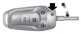
    Integrated Keyhead Transmitter (If Equipped)

    Use the key blade to start your vehicle and unlock or lock the driver door from outside your vehicle. The integrated keyhead transmitter functions as a programmed ignition key that operates all the locks and starts your vehicle, as well as a remote control.

    read more

     
    Copyright © 2024 www.foexplorer.com