Ford Explorer: Horn / Description and Operation - Horn - System Operation and Component Description
System Operation
System Diagram
.jpg)
| Item | Description |
|---|---|
| 1 | Clockspring |
| 2 | Horn Switch |
| 3 | SCCM |
| 4 | BCM |
| 5 | BCMC |
| 6 | Horn |
Horn Operation
The horn switch uses sets of contacts separated by springs. The lower set is connected to ground and the upper set is connected to the horn signal circuit. When the driver airbag is pressed, it pushes down on the upper set of contacts, collapsing the springs and allowing the contacts to touch. When the contacts touch, it completes the circuit and provides a ground signal through the clockspring to the BCM horn input. The BCM then grounds the integrated horn relay coil in the BCM-C to energize the non-serviceable relay. When energized, the horn relay provides voltage to the horn, enabling the horn to sound.
 Diagnosis and Testing - Horn
Diagnostic Trouble Code (DTC) Chart
Diagnostics in this manual assume a certain skill level and knowledge of Ford-specific diagnostic practices. REFER to: Diagnostic Methods (100-00 General Informati..
Other information:
Ford Explorer 2020-2026 Service Manual: Removal and Installation - Rear Door Window Glass
Removal NOTE: LH (left-hand) side shown, RH (right-hand) side similar. Remove the rear door glass top run. Refer to: Rear Door Glass Top Run (501-11 Glass, Frames and Mechanisms, Removal and Installation). Remove the rear door window glass...
Ford Explorer 2020-2026 Owners Manual: Audio Control
You can operate the following functions with the control: Press to decrease volume level. Press to increase volume level. Press to silence the current media Press to access phone mode or to answer a phone call. Press to end a phone call...
Categories
- Manuals Home
- 6th Generation Explorer Owners Manual
- 6th Generation Explorer Service Manual
- Electric Parking Brake
- Body and Paint
- Description and Operation - Identification Codes
- New on site
- Most important about car
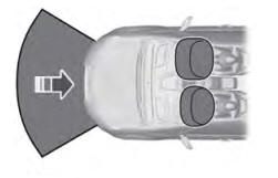
Driver and Passenger Airbags
WARNING: Do not place your arms on the airbag cover or through the steering wheel. Failure to follow this instruction could result in personal injury.
WARNING: Keep the areas in front of the airbags free from obstruction. Do not affix anything to or over the airbag covers. Objects could become projectiles during airbag deployment or in a sudden stop. Failure to follow this instruction could result in personal injury or death.
WARNING: Airbags can kill or injure a child in a child restraint. Never place a rear-facing child restraint in front of an active airbag. If you must use a forward-facing child restraint in the front seat, move the seat upon which the child restraint is installed all the way back.


.jpg)
