Ford Explorer: Police Equipment / Description and Operation - Flasher Lighting, Siren and Speaker System - System Operation and Component Description
System Operation
Description and Operation
Spotlamps
The LH and RH spotlamps are mounted on the A-pillers and are equipped with Light Emitting Diodes (LEDs). The spotlamps are provided battery voltage from BCMC fuse 108 (20A) and are grounded to the vehicle body through the spotlamp mount.
Flashing Light Emitting Diodes (LEDs)
The flashing Light Emitting Diodes (LEDs) are turned on and off by zones. There are 2 zones for the flashing Light Emitting Diodes (LEDs):
- Grille, headlamp, exterior mirror and, if equipped, front auxiliary flashing Light Emitting Diodes (LEDs)
- Rear lamp, rear quarter glass, high mount and liftgate (underside) flashing Light Emitting Diodes (LEDs)
When the lighting and siren control module receives a request from the control head for a group of flashing Light Emitting Diodes (LEDs), the lighting and siren control module sends voltage to that group of flashing Light Emitting Diodes (LEDs).
Traffic Control Flashing Light Emitting Diodes (LEDs)
The traffic control flashing Light Emitting Diodes (LEDs) are the LH and RH rear traffic control flashing Light Emitting Diodes (LEDs) mounted in the liftgate spoiler.
The traffic control flashing Light Emitting Diodes (LEDs) will display a variety of flashing and directional patterns as selected on the lighting and siren control module control head.
When the lighting and siren control module receives a request from the control head for a flashing or directional pattern, the lighting and siren control module sends voltage through a variety of circuits to the traffic control flashing LED control module. Then the traffic control flashing LED control module receives voltage in the input circuits indicating the requested flashing or directional pattern, the traffic control flashing LED control module sends the requested flashing or directional pattern over a LIN to each of the traffic control flashing Light Emitting Diodes (LEDs).
High Beam Wig-Wag Function
The high beams are alternately turned on and off by the wig-wag function. The wig-wag function is selected by the lighting and siren control module control head. When the wig-wag function is requested, a ground is provided to the BCM wig-wag input. Then the BCM sees this ground, it will turn on and off the high beams alternately using the vehicle high beam system.
Light Emitting Diodes (LEDs) Flash Patterns
The LED flash patterns are preset from the factory and can be changed in 2 groups.
Refer to: Group Flash Pattern Programming (100-05 Police Equipment, General Procedures).
The 2 groups are:
- Grille, exterior mirror and, if equipped, front auxiliary flashing Light Emitting Diodes (LEDs)
- Rear lamp, high mount and liftgate (underside) flashing Light Emitting Diodes (LEDs)
When a flashing LED is replaced, the flash pattern of the replacement LED may be different than the rest in the group.
Refer to: Individual Flash Pattern Programming (100-05 Police Equipment, General Procedures).
Flashing Light Emitting Diodes (LEDs) Synchronization
Some of the flashing Light Emitting Diodes (LEDs) are synchronized into 3 groups:
The 3 groups are:
- Grille, exterior mirror and, if equipped, front auxiliary flashing Light Emitting Diodes (LEDs)
- Rear lamp, high mount and liftgate (underside) flashing Light Emitting Diodes (LEDs)
- Headlamp flashing Light Emitting Diodes (LEDs)
Each flashing LED assembly contains a module that controls the flash pattern and synchronizes the flashing LED with the other flashing Light Emitting Diodes (LEDs) in the group.
Police Idle
The Police Idle system is activated and deactivated by pressing the Police Idle switch located on the LH lower instrument panel under the headlamp switch.
The switch can turn on the system any time, but will only activate when the vehicle has stopped and the gear selector is in PARK. The instrument panel indicator will illuminate yellow before the vehicle is in PARK and will illuminate green when in PARK.
Activate the system by following these steps in order:
- Place the gear selector is in PARK.
- Press the Police Idle switch (if not previously pressed).
- Wait for the indicator on the instrument panel to illuminate green.
- Place the ignition in OFF and remove the key.
While the system is active and the key is removed:
- The power window switches are disabled and the windows remain in their current state.
- The power door lock controls are disabled and all doors remain in their current locking state.
- The liftgate or luggage compartment switches are disabled.
- The vehicle will shutdown if the Police Idle switch is pressed.
- The vehicle will shutdown if the gear selector is moved from PARK.
Deactivate the system by following these steps in order:
- Insert the key and place the ignition in ON.
- Press the Police Idle switch.
- Wait for the indicator on the instrument panel to turn off.
Police Perimeter Alert System (if equipped)
The Police Perimeter Alert System is activated and deactivated by pressing the Police Perimeter Alert System switch located on the center of the instrument panel when the vehicle is running and is in PARK.
The Police Perimeter Alert system has three range settings Low, Medium or High via the menu in the instrument cluster display. Use the steering wheel controls to adjust the settings when active.
The Police Perimeter Alert system uses sensors located behind the rear bumper on both sides of your vehicle. The sensors will perform best if the vehicle is parked in an open area without large obstructions or walls nearby.
A pedestrian near large obstructions such as vehicles or walls may not be detected until the person moves away from the obstruction.
Sensor reflections from stationary objects may cause false objects to briefly appear on the Police Perimeter Alert System display.
Sensor obstructions such as; dirt, mud, precipitation, repair compound, stickers, graphics, bumper guards, trailers, or bicycle/cargo racks - in front of the sensors can cause system sensing degradation.
Component Description
Tail Lamp Flashing Light Emitting Diodes (LEDs)
The tail lamp flashing Light Emitting Diodes (LEDs) are mounted in the tail lamp assemblies. The tail lamp flashing Light Emitting Diodes (LEDs) operate independently of the park, turn and stoplamps.
Traffic Control Flashing Light Emitting Diodes (LEDs)
The traffic control lights consist of Light Emitting Diodes (LEDs) that flash in a variety of patterns and directions. They are controlled by the lighting and siren control module and traffic control flashing LED control module.
Traffic Control Flashing LED Control Module
The traffic control flashing LED control module controls the LIN circuit to the traffic control Light Emitting Diodes (LEDs).
Lighting And Siren Control Module
The lighting and siren control module controls the flashing Light Emitting Diodes (LEDs) and siren/speaker system. It uses a switch pad, installed by the customer, to control outputs to turn up to 4 flashing LED zones and the traffic adviser lights on and off. It also has a microphone input and a built-in amplifier to power the siren/speaker system.
The lighting and siren control module controls the siren/speaker system. It has a microphone input and a built-in amplifier to power the siren and speaker system.
Siren and Speaker System
The lighting and siren control module generates the siren pattern and receives input from the microphone and an output to the underhood siren speaker.
 Description and Operation - Flasher Lighting, Siren and Speaker System - Overview
Overview
Spotlamps
The
spotlamps provide an exterior illumination source that can be directed
by an interior control handle to illuminate the desired object...
 Diagnosis and Testing - Flasher Lighting, Siren and Speaker System
Diagnostic Trouble Code (DTC) Chart
Diagnostics in this manual assume a certain skill level and knowledge of Ford-specific diagnostic practices. REFER to: Diagnostic Methods (100-00 General Informati..
Other information:
Ford Explorer 2020-2025 Service Manual: Removal and Installation - Second Row Center Seatbelt Retractor
Removal NOTE: Removal steps in this procedure may contain installation details. NOTE: Base vehicle shown, police vehicle similar. Remove the second row center seat. Refer to: Second Row Center Seat (501-10B Second Row Seats, Removal and Installation)...
Ford Explorer 2020-2025 Service Manual: Removal and Installation - Front Door Window Glass
Removal NOTE: LH (left-hand) side shown, RH (right-hand) side similar. Remove the front door window regulator and motor. Refer to: Front Door Window Regulator and Motor (501-11 Glass, Frames and Mechanisms, Removal and Installation). Lower the front door glass to the full down position...
Categories
- Manuals Home
- 6th Generation Explorer Owners Manual
- 6th Generation Explorer Service Manual
- Fuel Filler Funnel Location & Running Out of Fuel
- Engine - 2.3L EcoBoost (201kW/273PS)
- Body and Paint
- New on site
- Most important about car
Windshield Wipers
 Push the lever up or down to operate
the windshield wipers.
Push the lever up or down to operate
the windshield wipers.
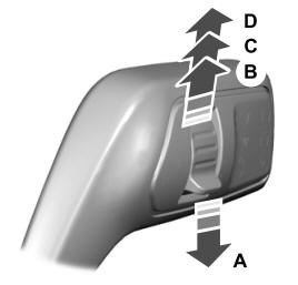
A - Single wipe.