Ford Explorer: Automatic Transmission - 10-Speed Automatic Transmission – 10R60 / Description and Operation - E Clutch
Overview
.jpg)
| Item | Description |
| 1 | SSE |
| 2 | E clutch control valve |
| 3 | Clutch gain control valve |
| 4 | E clutch apply circuit |
| 5 | E clutch piston |
| 6 | E clutch assembly |
| 7 | Shell and sun gear No. 4 |
Ring gear No. 3 is mechanically connected to sun gear No. 4 and both are connected to the E clutch. When the E clutch applies, torque from the input shaft is transferred to ring gear No. 3 and sun gear No. 4.
E Clutch Exploded View
.jpg)
| Item | Description |
| 1 | Ring gear No. 3 |
| 2 | E clutch hub |
| 3 | E clutch pressure plate (select fit) |
| 4 | E clutch friction plates (quantity model dependent) |
| 5 | E clutch steel plates (quantity model dependent) |
| 6 | E clutch apply plate (2.9-3.0 mm) |
| 7 | E clutch piston return spring |
| 8 | E clutch piston |
| 9 | E clutch balance dam |
| 10 | Shell and sun gear No. 4 |
E Clutch Hydraulic Circuits
.jpg)
| Item | Description |
| 1 | Line pressure |
| 2 | Pump output |
| 3 | E clutch control valve |
| 4 | SSE |
| 5 | D clutch control valve |
| 6 | SSD |
| 7 | D clutch apply pressure to clutch gain control valve |
| 8 | Clutch gain control valve |
| 9 | LPC solenoid |
| 10 | LPC pressure |
| 11 | E clutch feedback pressure |
| 12 | Apply pressure to mechanical E clutch |
| 13 | Mechanical E clutch |
| 14 | E clutch apply pressure to clutch gain control valve |
| 15 | D clutch feedback pressure |
| 16 | Elevated exhaust pressure |
| 17 | Clutch exhaust |
E Clutch Hydraulic Operation 5th-6th Shift
Line pressure is supplied to the E clutch control valve. LPC pressure is supplied to the gain control valve. LPC pressure positions the gain control valve to the right end of the valve bore. As SSE turns on, it moves the E clutch control valve allowing regulated line pressure to flow to the mechanical E clutch.
E Clutch Hydraulic Operation 2nd-3rd, 4th-5th, and 9th-10th Shifts
Line pressure is supplied to the E clutch control valve. LPC pressure is supplied to the gain control valve. The LPC pressure is low and the gain control valve stays in the default position at the left end of the valve bore. As SSE turns on, it moves the D clutch control valve allowing regulated line pressure to flow to the mechanical E clutch.
E Clutch Hydraulic Passages
.jpg)
.jpg)
.jpg)
 Description and Operation - D Clutch
Overview
Item
Description
1
SSD
2
D clutch control valve
3
Clutch gain control valve
4
D cl..
 Description and Operation - F Clutch
Overview
Item
Description
1
SSF
2
F clutch control valve
3
F clutch latch valve
4
F clutch ..
Other information:
Ford Explorer 2020-2026 Service Manual: Removal and Installation - Rear Halfshaft Seal
Special Tool(s) / General Equipment 205-153 (T80T-4000-W) Handle 307-758Installer, Axle Seal -FWD Feeler Gauge Flat Headed Screw Driver Removal NOTE: The stub shaft seals must be replaced whenever the halfshafts are removed...
Ford Explorer 2020-2026 Service Manual: Description and Operation - Interior Lighting - Overview
Overview The interior lighting system consists of: Courtesy lamps Demand lamps Ambient lighting The courtesy lamps subsystem consists of: Interior overhead lamps Puddle lamps Front door illuminated scuff plates Cargo lamp Courtesy lamp switch (integrated into the overhead console) Door ajar switches (integrated into the door latches) Liftgat..
Categories
- Manuals Home
- 6th Generation Explorer Owners Manual
- 6th Generation Explorer Service Manual
- Fuel Filler Funnel Location & Running Out of Fuel
- Automatic Transmission
- Body and Paint
- New on site
- Most important about car
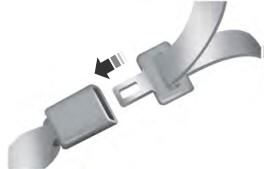
Fastening the Seatbelts
The front outboard and rear safety restraints in the vehicle are combination lap and shoulder belts.

