Ford Explorer: Power Steering / Removal and Installation - Tie Rod End
Ford Explorer 2020-2026 Service Manual / Chassis / Steering System / Power Steering / Removal and Installation - Tie Rod End
Special Tool(s) / General Equipment
| Tie Rod End Remover |
Removal
NOTE: Removal steps in this procedure may contain installation details.
-
Remove the wheel and tire.
Refer to: Wheel and Tire (204-04A Wheels and Tires, Removal and Installation).
-
-
Loosen the tie rod end jam nut.
Torque: 35 lb.ft (48 Nm)
-
Remove and discard the outer tie rod end nut.
Torque: 52 lb.ft (70 Nm)
-
NOTICE: Do not use a hammer to separate the outer tie-rod end from the wheel spindle or damage to the wheel spindle may result.
NOTICE: Use care when installing the tie rod separator or damage to the outer tie-rod end boot may occur.
Separate the outer tie rod end from the wheel knuckle.
Use the General Equipment: Tie Rod End Remover
-
Loosen the tie rod end jam nut.
.jpg) |
-
NOTE: Count and record the number of turns required to remove the outer tie-rod end for reference during installation.
Remove the tie-rod end.
.jpg) |
Installation
-
To install, reverse the removal procedure.
-
Check and if necessary, adjust front toe.
Refer to: Front Toe Adjustment (204-00 Suspension System - General Information, General Procedures).
 Removal and Installation - Tie Rod
Special Tool(s) /
General Equipment
Boot Clamp Pliers
Materials
Name
Specification
Motorcraft® Premium Long-Life GreaseXG-1-E1
ESA-M1C75-B
Removal
NOTICE:
When ..
Other information:
Ford Explorer 2020-2026 Service Manual: Removal and Installation - Fuel Pump Driver Module (FPDM)
Removal All Vehicles NOTE: The fuel pump driver module is located on the bottom side of the left front floor panel, above the sound insulation panel. For fuel pump driver module component location view. Refer to: Fuel Charging and Controls - Component Location (303-04A Fuel Charging and Controls - 2...
Ford Explorer 2020-2026 Owners Manual: About 911 Assist
911 Assist is a SYNC system feature that can call for help if you’re in an accident. If a crash deploys an airbag (excluding knee airbags and rear inflatable seatbelts [if equipped]) or activates the fuel pump shut-off, your SYNC-equipped vehicle may be able to contact emergency services by dialing 911 through a paired and connected Bluetooth-enabled phone...
Categories
- Manuals Home
- 6th Generation Explorer Owners Manual
- 6th Generation Explorer Service Manual
- Body and Paint
- Automatic Transmission
- Description and Operation - Jacking and Lifting - Overview
- New on site
- Most important about car
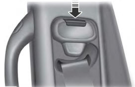
Seatbelt Height Adjustment
WARNING: Position the seatbelt height adjuster so that the seatbelt rests across the middle of your shoulder. Failure to adjust the seatbelt correctly could reduce its effectiveness and increase the risk of injury in a crash.

Copyright © 2026 www.foexplorer.com

