Ford Explorer: Third Row Seats / Removal and Installation - Third Row Seat Head Restraint
Ford Explorer 2020-2026 Service Manual / Body and Paint / Body and Paint / Third Row Seats / Removal and Installation - Third Row Seat Head Restraint
Special Tool(s) / General Equipment
| Interior Trim Remover |
Removal
-
Remove the third row seat backrest cover.
Refer to: Third Row Seat Backrest Cover (501-10C Third Row Seats, Removal and Installation).
-
Remove the third row seat backrest foam pin-type retainers.
.jpg) |
-
-
Route the head restraint manual release handle through the third row seat backrest foam.
-
Remove the third row seat backrest foam.
-
Route the head restraint manual release handle through the third row seat backrest foam.
.jpg) |
-
-
Cut the tie strap.
-
Detach the third row head restraint cable retainer.
Use the General Equipment: Interior Trim Remover
-
Rotate and disconnect the third row head restraint cable.
-
Cut the tie strap.
.jpg) |
-
If equipped.
-
Detach the third row head restraint cable retainer.
Use the General Equipment: Interior Trim Remover
-
Detach the third row head restraint cable from the bracket.
-
Detach the third row head restraint cable retainer.
.jpg) |
-
Remove the third row head restraint bolts.
Torque: 18 lb.ft (24 Nm)
.jpg) |
-
Remove the third row head restraint.
.jpg) |
Installation
-
To install, reverse the removal procedure.
 Removal and Installation - Third Row Seat Cushion Cover
Removal
Remove the third row seat cushion.
Refer to: Third Row Seat Cushion (501-10C Third Row Seats, Removal and Installation).
Release the retainers from the seat cushion f..

Other information:
Ford Explorer 2020-2026 Service Manual: General Procedures - Rear Toe Adjustment
Special Tool(s) / General Equipment Wheel Alignment System Adjustment NOTICE: Do not use any tools or equipment to move the wheel and tire assembly or suspension components while checking for relative movement. Suspension damage may occur...
Ford Explorer 2020-2026 Service Manual: Diagnosis and Testing - Rear Drive Halfshafts
Preliminary Inspection Visually inspect the CV joints, housing, boots, and clamps for obvious signs of mechanical damage. If an obvious cause for an observed or reported concern is found, correct the cause (if possible) before proceeding to the next step If the cause is not visually evident, verify the symptom and REFER to Symptom Chart: NVH...
Categories
- Manuals Home
- 6th Generation Explorer Owners Manual
- 6th Generation Explorer Service Manual
- Auxiliary Power Points
- Fuel Filler Funnel Location & Running Out of Fuel
- Driveline
- New on site
- Most important about car
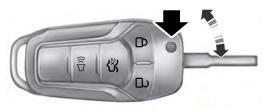
Integrated Keyhead Transmitter (If Equipped)
Use the key blade to start your vehicle and unlock or lock the driver door from outside your vehicle. The integrated keyhead transmitter functions as a programmed ignition key that operates all the locks and starts your vehicle, as well as a remote control.
Copyright © 2026 www.foexplorer.com