Ford Explorer: Climate Control System - General Information / Removal and Installation - Thermostatic Expansion Valve Manifold and Tube Assembly - 2.3L EcoBoost (201kW/273PS)
Ford Explorer 2020-2025 Service Manual / Electrical / Climate Control System / Climate Control System - General Information / Removal and Installation - Thermostatic Expansion Valve Manifold and Tube Assembly - 2.3L EcoBoost (201kW/273PS)
Removal
NOTICE: During the removal of components, cap, tape or otherwise appropriately protect all openings to prevent the ingress of dirt or other contamination. Remove protective materials prior to installation.
NOTE: Removal steps in this procedure may contain installation details.
-
Recover the refrigerant. Refer to the appropriate Recovery procedure in Group 412.
-
Disconnect the negative and positive battery cables.
Refer to: Battery Disconnect and Connect (414-01 Battery, Mounting and Cables, General Procedures).
-
Remove the bolts and the suspension support bar.
Torque: 22 lb.ft (30 Nm)
.jpg) |
-
Remove the PCM.
Refer to: Powertrain Control Module (PCM) (303-14A Electronic Engine Controls - 2.3L EcoBoost (201kW/273PS), Removal and Installation).
-
Detach the wiring harness routing clip and remove the PCM bracket.
Torque: 89 lb.in (10 Nm)
.jpg) |
-
Remove the cowl panel.
Refer to: Cowl Panel (501-02 Front End Body Panels, Removal and Installation).
-
-
Remove the bolt and position the ground aside.
Torque: 133 lb.in (15 Nm)
-
Remove the nuts and position the B+ battery cables aside.
Torque: 133 lb.in (15 Nm)
-
Remove the bolt and position the ground aside.
.jpg) |
-
Disconnect the wiring harness electrical connector.
.jpg) |
-
Position the wiring harness electrical grommet aside.
.jpg) |
-
-
Remove the condensor outlet line nut and position the line aside.
Torque: 80 lb.in (9 Nm)
-
Remove the A/Ccompressor inlet line nut and position the line aside.
Torque: 159 lb.in (18 Nm)
-
Make sure to cover any open ports to prevent debris from entering the system.
-
Remove the condensor outlet line nut and position the line aside.
.jpg) |
-
-
Remove the rear evaporator line nut.
Torque: 80 lb.in (9 Nm)
-
Remove the thermostatic expansion valve nut and the rear evaporator line nut.
Torque: 159 lb.in (18 Nm)
-
Remove the support bracket retainer.
Torque: 97 lb.in (11 Nm)
-
Make sure to cover any open ports to prevent debris from entering the system.
-
Remove the rear evaporator line nut.
.jpg) |
-
Remove the support bracket retainer and the thermostatic expansion valve manifold and tube assembly.
Torque: 97 lb.in (11 Nm)
.jpg) |
Installation
-
To install, reverse the removal procedure.
-
NOTICE: Only use the specified material to lubricate the seals.
Install and lubricate new O-ring seals. Refer to the appropriate Specifications in Group 412.
-
Lubricate the refrigerant system with the correct amount
of clean PAG oil. Refer to the appropriate Refrigerant Oil Adding
procedure in Group 412.
 Removal and Installation - Thermostatic Expansion Valve - 2.3L EcoBoost (201kW/273PS)
Removal
NOTICE:
During the removal of components, cap, tape or otherwise
appropriately protect all openings to prevent the ingress of dirt or
other contamination...
Other information:
Ford Explorer 2020-2025 Service Manual: Removal and Installation - Ignition Switch - Vehicles With: Keyless Vehicle System
Removal NOTE: Removal steps in this procedure may contain installation details. Release the clips and remove the trim panel. Remove the retainers. Torque: 22 lb.in (2.5 Nm) Release the clips and and position the instrument panel center trim panel aside...
Ford Explorer 2020-2025 Service Manual: Description and Operation - Four-Wheel Drive Systems - System Operation and Component Description
System Operation Principles of Operation The 4WD system is active all the time and requires no input from the driver. The 4WD system continuously monitors vehicle conditions and automatically applies torque to the front wheels when conditions or a drive mode selection commands it...
Categories
- Manuals Home
- 6th Generation Explorer Owners Manual
- 6th Generation Explorer Service Manual
- Removal and Installation - All-Wheel Drive (AWD) Module
- Engine
- Interior Trim and Ornamentation
- New on site
- Most important about car
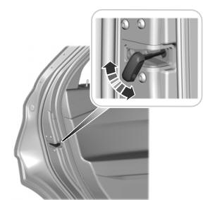
Child Safety Locks
When these locks are set, you cannot open the rear doors from the inside.

A child safety lock is on the rear edge of each rear door. You must set the child safety lock separately on each door.
Left-Hand Side
Copyright © 2025 www.foexplorer.com

