Ford Explorer: Rear Drive Axle/Differential / Removal and Installation - Rear Halfshaft Seal
Special Tool(s) / General Equipment
.jpg) |
205-153
(T80T-4000-W)
Handle |
.jpg) |
307-758 Installer, Axle Seal -FWD |
| Feeler Gauge | |
| Flat Headed Screw Driver | |
Removal
NOTE: The stub shaft seals must be replaced whenever the halfshafts are removed.
-
Remove the rear halfshaft.
Refer to: Rear Halfshaft (205-05 Rear Drive Halfshafts, Removal and Installation).
-
Remove and discard the rear halfshaft seal.
Use the General Equipment: Flat Headed Screw Driver
.jpg) |
Installation
-
Inspect the differential housing surface for rust, nicks
and scratches. Polish the differential housing surface with fine crocus
cloth, if necessary.
.jpg) |
-
NOTE: Installation of the halfshaft oil seal without the correct tools can result in early seal failure.
NOTE: Do not disassemble the new oil seal.
Install the new rear halfshaft seal onto a suitable special tool.
Use Special Service Tool: 307-758 Installer, Axle Seal -FWD. , 205-153 (T80T-4000-W) Handle.
.jpg) |
-
NOTICE: Strike only the handle. Directly striking the installer tool will damage the seal.
NOTE: Carefully align the halfshaft seal with the housing bore and ensure the seal should flush in the differential housing.
Install the new rear halfshaft seal.
Use Special Service Tool: 307-758 Installer, Axle Seal -FWD. , 205-153 (T80T-4000-W) Handle.
.jpg) |
-
NOTE: If a feeler gauge of the specification shown in the illustration can be inserted between the halfshaft oil seal and the differential housing, the halfshaft seal is not seated correctly. Remove the halfshaft oil seal and install a new halfshaft oil seal.
Make sure the stub shaft oil seal is correctly seated in the differential housing.
Use the General Equipment: Feeler Gauge
.jpg) |
-
Inspect the halfshaft seal lip for rust, nicks or
scratches prior to installing the halfshaft. Clean the seal lip with
fine crocus cloth, if required.
.jpg) |
-
Install the rear halfshaft.
Refer to: Rear Halfshaft (205-05 Rear Drive Halfshafts, Removal and Installation).
-
Check the differential fluid level.
Refer to: Differential Fluid Level Check (205-02 Rear Drive Axle/Differential, General Procedures).
 Removal and Installation - Drive Pinion Seal
Special Tool(s) /
General Equipment
205-1061Installer, Pinion Seal 8.8
205-1062Installer, Pinion Seal 8.15
205-199
(T83T-3132-A1)
Installer, Spindle/Axle ShaftT83-4000-ATKIT-198..
 Disassembly and Assembly - Differential Carrier
Special Tool(s) /
General Equipment
205-1016Installer, Differential BearingTKIT-2014D-ROW2TKIT-2014D-FL_ROW
205-153
(T80T-4000-W)
Handle
Two Leg Puller
DISASSEMBLY
..
Other information:
Ford Explorer 2020-2026 Service Manual: Removal and Installation - Keyless Entry Rear Antenna
Special Tool(s) / General Equipment Interior Trim Remover Removal Position the liftgate weatherstrip aside. Remove the liftgate scuff plate trim panel. Release the liftgate scuff plate trim panel clips...
Ford Explorer 2020-2026 Owners Manual: Fuel Consumption
Advertised Capacity The advertised capacity is the maximum amount of fuel that you can add to the fuel tank when the fuel gauge indicates empty. See Capacities and Specifications. In addition, the fuel tank contains an empty reserve. The empty reserve is an unspecified amount of fuel that remains in the fuel tank when the fuel gauge indicates empty...
Categories
- Manuals Home
- 6th Generation Explorer Owners Manual
- 6th Generation Explorer Service Manual
- Engine - 2.3L EcoBoost (201kW/273PS)
- Automatic Transmission
- Electric Parking Brake
- New on site
- Most important about car
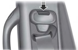
Seatbelt Height Adjustment
WARNING: Position the seatbelt height adjuster so that the seatbelt rests across the middle of your shoulder. Failure to adjust the seatbelt correctly could reduce its effectiveness and increase the risk of injury in a crash.

