Ford Explorer: Engine - 2.3L EcoBoost (201kW/273PS) / Removal and Installation - Intake Manifold
Materials
| Name |
Specification |
Motorcraft® Silicone Brake Caliper Grease and Dielectric Compound
XG-3-A |
ESE-M1C171-A
|
Removal
NOTICE:
The turbocharger compressor vanes can be damaged by even the
smallest particles. When removing any turbocharger or engine air intake
system component, ensure that no debris enters the system. Failure to
do so may result in damage to the turbocharger.
-
With the vehicle in NEUTRAL, position it on a hoist.
Refer to: Jacking and Lifting - Overview (100-02 Jacking and Lifting, Description and Operation).
-
Remove the bolts and the suspension support bar.
-
NOTICE:
Do not pull the engine appearance cover forward or
sideways to remove. Failure to press straight upward on the underside of
the cover at the attachment points may result in damage to the cover or
engine components.
-
Remove the engine appearance cover nuts.
-
Place your hand under the engine appearance cover at
the grommet location and push straight up to release the grommet from
the stud.
-
After the grommet has been released from the stud, remove the appearance cover from the engine.
-
Disconnect the battery ground.
Refer to: Battery Disconnect and Connect (414-01 Battery, Mounting and Cables - 2.3L EcoBoost (201kW/273PS))
.
-
Remove the following items:
-
Remove the cowl panel.
Refer to: Cowl Panel (501-02 Front End Body Panels, Removal and Installation).
-
Remove the EVAP canister purge valve.
Refer to: Evaporative Emission Canister Purge Valve (303-13A Evaporative Emissions - 2.3L EcoBoost (201kW/273PS), Removal and Installation).
-
Disconnect the EVAP canister tube quick release coupling and remove from the intake manifold.
Refer to: Quick Release Coupling (310-00 Fuel System - General Information - 2.3L EcoBoost (201kW/273PS))
.
-
Remove the bolt and position the coolant hose and bracket aside.
-
Loosen the CAC tube clamp and position aside.
-
Remove the bolts (Enhanced Hexalobular or TORX PLUS ®
Acument Intellectual Properties, LLC as the owner) and the shield.
-
Detach the retainers, remove the bolt and position the ground wire aside.
-
-
Disconnect the wiring harness electrical connectors.
-
Detach the wiring harness retainers.
-
Detach the fuel rail wiring harness retainer from the intake manifold.
-
If equipped, detach the block heater wiring harness retainer from the intake manifold.
-
-
Loosen the clamps and remove the EGR transducer hoses.
-
Remove the bolt and the EGR transducer assembly.
-
Detach the coolant hose retainer from the bottom of intake manifold.
-
Remove the nuts, bolt and position the EGR inlet tube assembly from intake manifold.
-
Remove and discard the EGR inlet tube assembly gasket.
-
-
Disconnect the crankcase vent oil separator tube quick release coupling from the intake manifold.
Refer to: Quick Release Coupling (310-00 Fuel System - General Information - 2.3L EcoBoost (201kW/273PS))
.
-
Remove the bolts and position the intake manifold forward.
-
Detach the KS electrical connector retainers and remove the intake manifold.
-
NOTICE:
If the engine is repaired or replaced because of
upper engine failure, typically including valve or piston damage, check
the intake manifold for metal debris. If metal debris is found, install a
new intake manifold. Failure to follow these instructions can result in
engine damage.
-
Visually inspect the intake manifold for metal debris.
-
-
Visually inspect the intake manifold gaskets for
nicks, cuts and abrasions. If these conditions are not present, the
gaskets may be reused.
-
Clean and inspect all of the sealing surfaces of the intake manifold.
Installation
-
Inspect the turbocharger or engine air intake system components and clean, if necessary.
-
Install the intake manifold and attach the KS electrical connector retainers.
-
-
Position the intake manifold and install the bolts and tighten in sequence shown.
Torque:
18 lb.ft (25 Nm)
-
Connect the crankcase vent oil separator tube quick release coupling to the intake manifold.
Refer to: Quick Release Coupling (310-00 Fuel System - General Information - 2.3L EcoBoost (201kW/273PS))
.
-
Install a new EGR inlet tube assembly gasket.
-
Position the EGR inlet tube assembly to intake manifold and install the nuts and bolt and tighten in sequence shown.
Torque:
97 lb.in (11 Nm)
-
Attach the coolant hose retainer to the bottom of intake manifold.
-
-
Install the EGR transducer assembly and the bolt.
Torque:
97 lb.in (11 Nm)
-
Install the EGR transducer hoses.
-
If equipped, attach the block heater wiring harness retainer to the intake manifold.
-
Attach the fuel rail wiring harness retainer to the intake manifold.
-
-
Connect the wiring harness electrical connectors.
-
Attach the wiring harness retainers.
-
Position the ground wire and install the bolt and attach the retainers.
Torque:
159 lb.in (18 Nm)
-
Install the shield and the bolts (Enhanced Hexalobular
or TORX PLUS ® Acument Intellectual Properties, LLC as the owner).
Torque:
18 lb.ft (25 Nm)
-
Position the CAC tube and tighten the clamp.
Torque:
44 lb.in (5 Nm)
-
Position the coolant hose and bracket and install the bolt.
Torque:
97 lb.in (11 Nm)
-
Install the EVAP canister tube and connect the quick release coupling to the intake manifold.
Refer to: Quick Release Coupling (310-00 Fuel System - General Information - 2.3L EcoBoost (201kW/273PS))
.
-
Install the following items:
-
Install the EVAP canister purge valve.
Refer to: Evaporative Emission Canister Purge Valve (303-13A Evaporative Emissions - 2.3L EcoBoost (201kW/273PS), Removal and Installation).
-
Install the cowl panel.
Refer to: Cowl Panel (501-02 Front End Body Panels, Removal and Installation).
-
Connect the battery ground.
Refer to: Battery Disconnect and Connect (414-01 Battery, Mounting and Cables - 2.3L EcoBoost (201kW/273PS))
.
-
-
NOTE:
Lubricating the grommets with silicone grease
will aid in the installation of the engine appearance cover, and any
future removal and installation of the cover.
Lubricate each grommet with silicone grease.
Material: Motorcraft® Silicone Brake Caliper Grease and Dielectric Compound
/ XG-3-A
(ESE-M1C171-A)
-
Position the engine appearance cover onto engine with the grommet aligned with the stud.
-
Press down on the engine appearance cover at the
grommet location to attach the grommet onto the stud and install the
nuts.
Torque:
44 lb.in (5 Nm)
-
Install the suspension support bar and the bolts.
Torque:
22 lb.ft (30 Nm)
Special Tool(s) /
General Equipment
303-103
(T74P-6375-A)
Holding Tool, FlywheelT74P-77000-ATKIT-2009TC-F
Removal
With the vehicle in NEUTRAL, position it on a hoist...
Special Tool(s) /
General Equipment
Hose Clamp Remover/Installer
Locking Pliers
Removal
NOTE:
During engine repair procedures, cleanliness is extremely
important...
Other information:
Special Tool(s) /
General Equipment
Interior Trim Remover
Removal
Remove the sunload sensor from the instrument panel.
Disconnect the electrical connector.
Use the General Equipment: Interior Trim Remover
Installation
To install, reverse the removal procedure...
WARNING: Always drive and ride with your seatback upright and the lap belt
snug and low across the hips.
WARNING: Children must always be properly restrained.
WARNING: Do not allow a passenger to hold a child on their lap when your
vehicle is moving...
Categories
 Push the lever up or down to operate
the windshield wipers.
Push the lever up or down to operate
the windshield wipers.
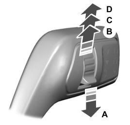
A - Single wipe.
read more
.jpg)
.jpg)
.jpg)
.jpg)
.jpg)
.jpg)
.jpg)
.jpg)
.jpg)
.jpg)
.jpg)
.jpg)
.jpg)
.jpg)
.jpg)
.jpg)
.jpg)
.jpg)
.jpg)
.jpg)
.jpg)
.jpg)
 Removal and Installation - Flexplate
 Removal and Installation - Oil Cooler