Ford Explorer: High Voltage Battery, Mounting and Cables / Removal and Installation - High Voltage High Current Fuse - Hybrid Electric Vehicle (HEV)
Removal
 WARNING:
To prevent the risk of high-voltage shock, always follow
precisely all warnings and service instructions, including instructions
to depower the system. The high-voltage system utilizes approximately
450 volts DC, provided through high-voltage cables to its components and
modules. The high-voltage cables and wiring are identified by orange
harness tape or orange wire covering. All high-voltage components are
marked with high-voltage warning labels with a high-voltage symbol.
Failure to follow these instructions may result in serious personal
injury or death.
-
Refer to: Health and Safety Precautions (100-00 General Information, Description and Operation).
WARNING:
Before beginning any service procedure in this
section, refer to Safety Warnings in section 100-00 General Information.
Failure to follow this instruction may result in serious personal
injury.
-
Remove the high voltage battery.
Refer to: High Voltage Battery - Hybrid Electric Vehicle (HEV) (414-03 High Voltage Battery, Mounting and Cables, Removal and Installation).
-
Remove the fasteners and the high voltage battery cover.
 |
-
Disconnect the electrical connectors.
 |
-
NOTE: Use a fuse puller standard tool, or pry it out with a flathead screwdriver.
Remove the high current fuse.
 |
Installation
-
To install, reverse the removal procedure.
-
The fasteners must be installed by hand before final tightening.
Tighten the fasteners in sequence shown in 2 stages.
Torque:
Stage 1: 62 lb.in (7 Nm)
Stage 2: 177 lb.in (20 Nm)
 |
-
Install the high voltage battery.
Refer to: High Voltage Battery - Hybrid Electric Vehicle (HEV) (414-03 High Voltage Battery, Mounting and Cables, Removal and Installation).
 Removal and Installation - High Voltage Low Current Fuse - Hybrid Electric Vehicle (HEV)
Removal
WARNING:
To prevent the risk of high-voltage shock, always follow
precisely all warnings and service instructions, including instructions
to depower the system...
 Removal and Installation - High Voltage Battery Coolant Cover - Hybrid Electric Vehicle (HEV)
Special Tool(s) /
General Equipment
Locking Pliers
Removal
WARNING:
To prevent the risk of high-voltage shock, always follow
precisely all warnings and service instructions, in..
Other information:
Ford Explorer 2020-2026 Service Manual: Removal and Installation - Second Row Seat Cushion Blower Motor
Removal NOTE: Removal steps in this procedure may contain installation details. Remove the second row single seat cushion cover. Refer to: Second Row Single Seat Cushion Cover - Vehicles With: Second Row Captain Chairs (501-10B Second Row Seats, Removal and Installation)...
Ford Explorer 2020-2026 Owners Manual: Adaptive Cruise Control Limitations - Vehicles With: Adaptive Cruise Control With Stop and Go
Sensor Limitations WARNING: On rare occasions, detection issues can occur due to the road infrastructures, for example bridges, tunnels and safety barriers. In these cases, the system may brake late or unexpectedly. At all times, you are responsible for controlling your vehicle, supervising the system and intervening, if required...
Categories
- Manuals Home
- 6th Generation Explorer Owners Manual
- 6th Generation Explorer Service Manual
- Traction Control
- Engine - 2.3L EcoBoost (201kW/273PS)
- Description and Operation - Identification Codes
- New on site
- Most important about car
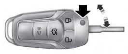
Integrated Keyhead Transmitter (If Equipped)
Use the key blade to start your vehicle and unlock or lock the driver door from outside your vehicle. The integrated keyhead transmitter functions as a programmed ignition key that operates all the locks and starts your vehicle, as well as a remote control.