Ford Explorer: High Voltage Battery, Mounting and Cables / Removal and Installation - High Voltage Battery Junction Box - Hybrid Electric Vehicle (HEV)
Removal
.jpg) WARNING:
To prevent the risk of high-voltage shock, always follow
precisely all warnings and service instructions, including instructions
to depower the system. The high-voltage system utilizes approximately
450 volts DC, provided through high-voltage cables to its components and
modules. The high-voltage cables and wiring are identified by orange
harness tape or orange wire covering. All high-voltage components are
marked with high-voltage warning labels with a high-voltage symbol.
Failure to follow these instructions may result in serious personal
injury or death.
WARNING:
To prevent the risk of high-voltage shock, always follow
precisely all warnings and service instructions, including instructions
to depower the system. The high-voltage system utilizes approximately
450 volts DC, provided through high-voltage cables to its components and
modules. The high-voltage cables and wiring are identified by orange
harness tape or orange wire covering. All high-voltage components are
marked with high-voltage warning labels with a high-voltage symbol.
Failure to follow these instructions may result in serious personal
injury or death.
-
Refer to: Health and Safety Precautions (100-00 General Information, Description and Operation)..jpg) WARNING:
Before beginning any service procedure in this
section, refer to Safety Warnings in section 100-00 General Information.
Failure to follow this instruction may result in serious personal
injury.
WARNING:
Before beginning any service procedure in this
section, refer to Safety Warnings in section 100-00 General Information.
Failure to follow this instruction may result in serious personal
injury.
-
Remove the high voltage battery.
Refer to: High Voltage Battery - Hybrid Electric Vehicle (HEV) (414-03 High Voltage Battery, Mounting and Cables, Removal and Installation).
-
Remove the fasteners and the high voltage battery cover.
.jpg) |
-
-
Disconnect the electrical connectors.
-
Release the wire guides and position aside the harness.
-
Disconnect the electrical connectors.
.jpg) |
-
Disconnect the electrical connectors and position aside the harness.
.jpg) |
-
Remove the bolts.
Torque: 62 lb.in (7 Nm)
.jpg) |
-
Remove the bolt and the high voltage battery junction box
Torque: 62 lb.in (7 Nm)
.jpg) |
Installation
-
NOTE: Make sure that the high voltage battery junction box has the seals pressed in place.
.jpg) |
-
To install, reverse the removal procedure.
-
The fasteners must be installed by hand before final tightening.
Tighten the fasteners in sequence shown in 2 stages.
Torque:
Stage 1: 62 lb.in (7 Nm)
Stage 2: 177 lb.in (20 Nm)
.jpg) |
-
Install the high voltage battery.
Refer to: High Voltage Battery - Hybrid Electric Vehicle (HEV) (414-03 High Voltage Battery, Mounting and Cables, Removal and Installation).
 Removal and Installation - Battery Energy Control Module (BECM) - Hybrid Electric Vehicle (HEV)
Special Tool(s) /
General Equipment
Ford Diagnostic Equipment
Removal
WARNING:
To prevent the risk of high-voltage shock, always follow
precisely all warnings and service instr..
 Removal and Installation - High Voltage Low Current Fuse - Hybrid Electric Vehicle (HEV)
Removal
WARNING:
To prevent the risk of high-voltage shock, always follow
precisely all warnings and service instructions, including instructions
to depower the system...
Other information:
Ford Explorer 2020-2025 Service Manual: Removal and Installation - High Mounted Flashing Light Emitting Diode (LED) Lamps
Removal NOTE: Removal steps in this procedure may contain installation details. NOTE: LH side shown, RH is similar. Remove the screws and the trim cover. Torque: 20 lb.in (2.3 Nm) Remove the liftgate trim panel...
Ford Explorer 2020-2025 Service Manual: Specifications
Engine Item Specification Displacement 140 in³ ( 2.3 L) No. of cylinders 4 Bore 3.4449 in ( 87.5 mm) Stroke 3.7008 in ( 94 mm) Firing order 1-3-4-2 Compression ratio 10...
Categories
- Manuals Home
- 6th Generation Explorer Owners Manual
- 6th Generation Explorer Service Manual
- Fuel Filler Funnel Location & Running Out of Fuel
- Using Tether Straps
- Automatic Transmission - 10-Speed Automatic Transmission – 10R60
- New on site
- Most important about car
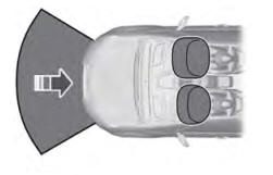
Driver and Passenger Airbags
WARNING: Do not place your arms on the airbag cover or through the steering wheel. Failure to follow this instruction could result in personal injury.
WARNING: Keep the areas in front of the airbags free from obstruction. Do not affix anything to or over the airbag covers. Objects could become projectiles during airbag deployment or in a sudden stop. Failure to follow this instruction could result in personal injury or death.
WARNING: Airbags can kill or injure a child in a child restraint. Never place a rear-facing child restraint in front of an active airbag. If you must use a forward-facing child restraint in the front seat, move the seat upon which the child restraint is installed all the way back.

