
Ford Explorer: Front Drive Axle/Differential / Removal and Installation - Axle Shaft Seal
Ford Explorer 2020-2026 Service Manual / Chassis / Driveline / Front Drive Axle/Differential / Removal and Installation - Axle Shaft Seal
Special Tool(s) / General Equipment
.jpg) |
205-907 Handle, 32 Driver TKIT-2008DH-FLM |
.jpg) |
307-256
(T92P-77000-FH)
Installer, Differential Fluid Seal TKIT-1992-FLMH/LMH |
Removal
-
NOTE: The stub shaft seals must be replaced whenever the halfshafts are removed.
Remove the front RH halfshaft.
Refer to: Halfshaft (205-04 Front Drive Halfshafts, Removal and Installation).
-
Remove and discard the front RH halfshaft seal.
.jpg) |
Installation
-
Inspect the differential housing surface for rust, nicks
and scratches. Polish the differential housing surface with fine crocus
cloth, if necessary.
.jpg) |
-
NOTE: Installation of the halfshaft oil seal without the correct tools can result in early seal failure.
NOTE: Do not disassemble the new oil seal.
Install the new seal onto a suitable special tool.
Use Special Service Tool: 307-256 (T92P-77000-FH) Installer, Differential Fluid Seal. , 205-907 Handle, 32 Driver.
.jpg) |
-
NOTICE: Strike only the handle. Directly striking the installer tool will damage the seal.
NOTE: Carefully align the halfshaft seal with the housing bore and ensure the seal should flush in the differential housing.
Using special tools, install the new front RH halfshaft seal.
Use Special Service Tool: 307-256 (T92P-77000-FH) Installer, Differential Fluid Seal. , 205-907 Handle, 32 Driver.
.jpg) |
-
Inspect the halfshaft seal lip for rust, nicks or
scratches prior to installing the halfshaft. Clean the seal lip with
fine crocus cloth, if required.
.jpg) |
-
Install the front RH halfshaft.
Refer to: Halfshaft (205-04 Front Drive Halfshafts, Removal and Installation).
-
Check the differential fluid level.
Refer to: Differential Fluid Level Check (205-03 Front Drive Axle/Differential, General Procedures).
 Removal and Installation - Axle Assembly
Materials
Name
Specification
Slip Yoke Grease5L3Z-19A506-A
-
Removal
Drain the front differential fluid.
Refer to: Differential Draining and Filling (205-03 Front Dr..
 Removal and Installation - Differential Breather Tube
Removal
NOTE:
Removal steps in this procedure may contain installation details.
Remove the front RH wheel only.
Refer to: Wheel and Tire (204-04A Wheels and Tires, Removal and Installa..
Other information:
Ford Explorer 2020-2026 Service Manual: Removal and Installation - Rear Side Marker Flashing Light Emitting Diode (LED) Lamps
Special Tool(s) / General Equipment Interior Trim Remover Removal NOTE: Removal steps in this procedure may contain installation details. NOTE: LH lamp assembly shown, RH lamp assembly is similar. Remove the loadspace trim panel...
Ford Explorer 2020-2026 Service Manual: Description and Operation - Information and Entertainment System - Component Location
N..
Categories
- Manuals Home
- 6th Generation Explorer Owners Manual
- 6th Generation Explorer Service Manual
- Automatic Transmission
- Body and Paint
- Description and Operation - Identification Codes
- New on site
- Most important about car
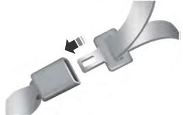
Fastening the Seatbelts
The front outboard and rear safety restraints in the vehicle are combination lap and shoulder belts.

Copyright © 2026 www.foexplorer.com