Ford Explorer: General Information / General Procedures - Wire Terminal Inspection and Removal
Disconnect
-
Refer to: Health and Safety Precautions (100-00 General Information, Description and Operation)..jpg) WARNING:
Before beginning any service procedure in this
section, refer to Health and Safety Precautions in section 100-00
General Information. Failure to follow this instruction may result in
serious personal injury.
WARNING:
Before beginning any service procedure in this
section, refer to Health and Safety Precautions in section 100-00
General Information. Failure to follow this instruction may result in
serious personal injury.
NOTE: To avoid wiring pin (terminal) damage, Rotunda Flex Probes NUD105-R025D or Terminal Probe Kit 29-011A must be used to connect test equipment or jumper wires to pins (terminals).
- Male to female pin (terminal) fit is critical for correct connection and durability.
- Pin (terminal) fit may be checked by using the mating pin (terminal) to test for normal separation force (a damaged pin or terminal will have very low separation force from the mating pin or terminal).
- Correctly checking the separation force of small pins (terminals) may require removal of the connector terminal guide/retainer if it adds drag to the pin (terminal) insertion or removal.
- For more detail on the replacement of damaged connectors or pins (terminals) refer to the video below.
Click here to view a video version of this procedure.

-
NOTE: The connector hard-shell information, which is measured in millimeters is the distance from the front face of the connector to the engagement point on the terminal release tang. Mark the listed distance on the terminal removal tool prior to removing the terminal.
NOTE: The dimensions of the connector hard-shell and the connector terminals release tang are listed above the corresponding graphics.
-
Audio Front Control Module (ACM), Body Control Module (BCM) and Instrument Panel Cluster (IPC) Electrical Connector
Callout Connector 1 External terminal release tang 2 Electrical connector locking tab
.jpg) |
-
Audio Front Control Module (ACM), Front Controls Interface Module (FCIM), Gateway Module A (GWM), and Heating, Ventilation and Air Conditioning (HVAC) Control Module Electrical Connector
Callout Connector 1 Distance to release tang - 0.2953 in ( 7.5 mm) (inner terminal) - 0.4646 in ( 11.8 mm) (outer terminal) 2 Terminal width size - 0.0244 in ( .62 mm) (inner terminal) - 0.1102 in ( 2.8 mm) (outer terminal)
.jpg) |
-
Body Control Module (BCM) Electrical Connector
Callout Connector 1 Terminal width size - 0.1102 in ( 2.8 mm) (inner terminal) - 0.2480 in ( 6.3 mm) (outer terminal) 2 Distance to release tang - 0.1260 in ( 3.2 mm) (inner terminal) - 0.1575 in ( 4 mm) (outer terminal) 3 Terminal width size - 0.0591 in ( 1.5 mm) 4 Distance to release tang - 0.3780 in ( 9.6 mm) (lower terminal)
.jpg) |
-
Body Control Module (BCM) Electrical Connector
Callout Connector 1 Terminal width size - 0.0591 in ( 1.5 mm) (inner terminal) - 0.1102 in ( 2.8 mm) (outer terminal) 2 Distance to release tang - 0.3780 in ( 9.6 mm) (inner terminal) 3 Distance to release tang - 0.1575 in ( 4 mm) 4 Distance to release tang - 0.1575 in ( 4 mm) 5 Terminal width size - 0.2480 in ( 6.3 mm)
.jpg) |
-
Body Harness In-line Electrical Connector
Callout Connector 1 Distance to release tang - 0.3346 in ( 8.5 mm) 2 Terminal width size - 0.1102 in ( 2.8 mm) 3 Terminal width size - 0.0591 in ( 1.5 mm) 4 Distance to release tang - 0.3858 in ( 9.8 mm) (inner)
.jpg) |
-
Body Harness In-line Electrical Connector
Callout Connector 1 Distance to release tang - 0.3543 in ( 9 mm) 2 Terminal width size - 0.0591 in ( 1.5 mm) (inner terminal) - 0.1102 in ( 2.8 mm) (outer terminal) 3 Terminal width size - 0.2480 in ( 6.3 mm) 4 Distance to release tang - 0.3543 in ( 9 mm)
.jpg) |
-
Body Harness In-line and Seat Harness Electrical Connector
Callout Connector 1 Distance to release tang - 0.4331 in ( 11 mm) 2 Terminal width size - 0.0591 in ( 1.5 mm) 3 Terminal width size - 0.0591 in ( 1.5 mm) 4 Distance to release tang - 0.4331 in ( 11 mm)
.jpg) |
-
Body Harness In-line and Seat Module Electrical Connector
Callout Connector 1 Terminal width size - 0.0591 in ( 1.5 mm) 2 Distance to release tang - 0.3937 in ( 10 mm)
.jpg) |
 Description and Operation - Wheel and Tire Health and Safety Precautions
WARNING:
Never inflate a tire that has been run flat without first
removing the tire from the wheel to inspect for damage. A damaged tire
can fail during inflation...

Other information:
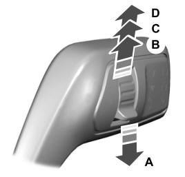
Ford Explorer 2020-2026 Owners Manual: Rear Window Wiper and Washers
Rear Window Wiper A - Intermittent wipe. B - Continuous wipe. C - Rear window wiper off. Depending on your vehicle, when you switch on the front wipers and move the gearshift lever to reverse (R), the rear intermittent wipe may turn on. Note: Make sure you switch the rear window wiper off before entering a car wash...
Ford Explorer 2020-2026 Service Manual: General Procedures - Power Door Window Initialization
Initialization WARNING: Before beginning any service procedure in this section, refer to Safety Warnings in section 100-00 General Information. Failure to follow this instruction may result in serious personal injury. Refer to: Health and Safety Precautions (100-00 General Information, Description and Operation)...
Categories
- Manuals Home
- 6th Generation Explorer Owners Manual
- 6th Generation Explorer Service Manual
- Body and Paint
- Removal and Installation - All-Wheel Drive (AWD) Module
- Description and Operation - Identification Codes
- New on site
- Most important about car
Windshield Wipers
 Push the lever up or down to operate
the windshield wipers.
Push the lever up or down to operate
the windshield wipers.
A - Single wipe.