Ford Explorer: Engine - 2.3L EcoBoost (201kW/273PS) / General Procedures - Valve Clearance Adjustment
Special Tool(s) / General Equipment
| Feeler Gauge |
Check
-
Remove the valve cover.
Refer to: Valve Cover (303-01A Engine - 2.3L EcoBoost (201kW/273PS), Removal and Installation).
-
NOTE: Turn the engine clockwise only, and only use the crankshaft bolt.
NOTE: Measure the clearance of each valve at base circle, with the lobe pointed away from the tappet.
Use a feeler gauge to measure the clearance of each valve and record its location.
Use the General Equipment: Feeler Gauge
.jpg) |
-
Valve tappet assembly grade chart
-
Grade
-
Id Mark
-
Thickness (mm)
-
Grade
.jpg) |
-
NOTE: There are two numbers on the valve tappet, one is date code and the other is valve tappet thickness.
NOTE: The date code “R0605” represents the year made (R), the month (06) and the day (05).
NOTE: A tappet with the number N650 has the thickness of 3.650 mm.
NOTE: Select tappets using this formula: tappet thickness = measured clearance + the existing tappet thickness - nominal clearance.
NOTE: The nominal clearance is:
- intake: 0.25 mm (0.0095 in).
- exhaust: 0.36 mm (0.0142 in).
NOTE: The acceptable clearances after being fully installed are:
- intake: 0.19-0.31 mm (0.0075-0.0122 in).
- exhaust: 0.3-0.42 mm (0.0118-0.0165 in).
-
If any tappets do not measure within specifications, install new tappets in these locations.
Adjustment
-
NOTE: The following step is only necessary if adjustment is required.
Remove the camshafts.
Refer to: Camshafts (303-01A Engine - 2.3L EcoBoost (201kW/273PS), Removal and Installation).
 General Procedures - Engine Oil Draining and Filling
Special Tool(s) /
General Equipment
Oil Drain Equipment
Draining
With the vehicle in NEUTRAL, position it on a hoist.
Refer to: Jacking and Lifting - Overview (100-02 Jacking an..
 Removal and Installation - Camshafts
Special Tool(s) /
General Equipment
303-1685Alignment Tool, Camshaft
303-507Timing Peg, Crankshaft TDCTKIT-2001N-FLMTKIT-2001N-ROW
Feeler Gauge
Removal
NOTE:
During engin..
Other information:
Ford Explorer 2020-2026 Service Manual: Removal and Installation - Loadspace Trim Panel - Police
Special Tool(s) / General Equipment Interior Trim Remover Removal NOTE: RH (right hand) shown, LH (left hand) similar. Remove the D-pillar trim panel. Refer to: D-Pillar Trim Panel - Police (501-05 Interior Trim and Ornamentation, Removal and Installation)...
Ford Explorer 2020-2026 Owners Manual: Climate Controlled Seats (If Equipped)
Heated Seats WARNING: Use caution when using the heated seat if you are unable to feel pain to your skin because of advanced age, chronic illness, diabetes, spinal cord injury, medication, alcohol use, exhaustion or other physical conditions. The heated seat could cause burns even at low temperatures, especially if used for long periods of time...
Categories
- Manuals Home
- 6th Generation Explorer Owners Manual
- 6th Generation Explorer Service Manual
- Removal and Installation - Front Halfshaft Speed Sensor
- Automatic Transmission
- General Service Information
- New on site
- Most important about car
Windshield Wipers
 Push the lever up or down to operate
the windshield wipers.
Push the lever up or down to operate
the windshield wipers.
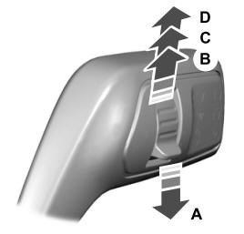
A - Single wipe.