Ford Explorer: Instrument Panel and Interior Switches Illumination / Description and Operation - Instrument Panel and Interior Switches Illumination - Overview
Overview
Dimmable Illumination
Dimmable illumination provides backlighting to switches and control components when the parking lamps are on. The instrument panel dimmer switch is used to increase or decrease the level of intensity for the dimmable backlit components. The BCM is the master module that controls the dimmable illumination.
Dimmable backlit switches and components are:
- Headlamp switch
- EPB switch
- Overhead console switches
- USB hub
- Start-stop switch
- 4X4 switch
- Drive mode switch
- High idle switch (police package)
- Lighting/siren control module (police package)
- Steering wheel switches
- Emergency call switch
- Power window switches
- Door lock switches
When the autolamp feature activates during the daytime, the message center illumination remains at full intensity and can not be dimmed using the instrument panel dimmer switch. If the vehicle travels under a bridge or through a tunnel and a low level of ambient light is detected, the illumination brightness of the message center changes to the last level set by BCM. The message center illumination changes back to full intensity when the intense ambient light is restored.
Non-Dimmable Illumination
The non-dimmable illumination is on when the delayed accessory is active. The delayed accessory is active:
- When the ignition is on.
- For up to 10 minutes after the ignition is cycled from on to off and a front door is not opened.
The second row rear seat control, third row rear seat control and liftgate release switches are non-dimmable.

 Description and Operation - Instrument Panel and Interior Switches Illumination - System Operation and Component Description
System Operation
System Diagram - Networked Illumination
Item
Description
1
APIM
2
Light Sensor
3
ACM
4
IPC
5
FDIM
6
DDM
..
Other information:
Ford Explorer 2020-2024 Service Manual: Description and Operation - Power Steering - System Operation and Component Description
System Operation System Diagram Item Description 1 EPAS gear 2 EPAS motor 3 EPAS position sensor 4 EPAS torque sensor 5 PSCM 6 GWM 7 PCM 8 IPC 9 BCM 10 RCM 11 ABS module 12 IPMB 13 IPMA 14 SCCM 15 PAM Network Message Chart ..
Ford Explorer 2020-2024 Owners Manual: About Drive Mode Control
The system delivers a driving experience through a suite of sophisticated electronic vehicle systems. These systems optimize steering, handling and powertrain response. This provides a single location to control multiple systems performance settings...
Categories
- Manuals Home
- 6th Generation Explorer Owners Manual
- 6th Generation Explorer Service Manual
- Removal and Installation - Liftgate Trim Panel
- Body and Paint
- Engine
- New on site
- Most important about car
Windshield Wipers
 Push the lever up or down to operate
the windshield wipers.
Push the lever up or down to operate
the windshield wipers.
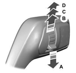
A - Single wipe.