Ford Explorer: Engine - 2.3L EcoBoost (201kW/273PS) / Removal and Installation - Valve Cover
Special Tool(s) /
General Equipment
.jpg) |
205-153
(T80T-4000-W)
Handle |
.jpg) |
303-1687
Installer, VCT Solenoid Seal |
| Side Cutter Pliers |
| Hose Clamp Remover/Installer |
Materials
| Name |
Specification |
Motorcraft® High Performance Engine RTV Silicone
TA-357 |
WSE-M4G323-A6
|
Motorcraft® Silicone Brake Caliper Grease and Dielectric Compound
XG-3-A |
ESE-M1C171-A
|
Removal
NOTICE:
During engine repair procedures, cleanliness is extremely
important. Any foreign material, including any material created while
cleaning gasket surfaces, that enters the oil passages, coolant passages
or the oil pan can cause engine failure.
-
With the vehicle in NEUTRAL, position it on a hoist.
Refer to: Jacking and Lifting - Overview (100-02 Jacking and Lifting, Description and Operation).
-
Release the fuel system pressure.
Refer to: Fuel System Pressure Release (310-00A Fuel System - General Information - 2.3L EcoBoost (201kW/273PS), General Procedures).
-
Disconnect the battery ground cable.
Refer to: Battery Disconnect and Connect (414-01 Battery, Mounting and Cables, General Procedures).
-
Remove the bolts and the suspension support bar.
-
NOTICE:
Do not pull the engine appearance cover forward or
sideways to remove. Failure to press straight upward on the underside of
the cover at the attachment points may result in damage to the cover or
engine components.
-
Remove the engine appearance cover nuts.
-
Place your hand under the engine appearance cover at
the grommet location and push straight up to release the grommet from
the stud.
-
After the grommet has been released from the stud, remove the appearance cover from the engine.
-
Drain the cooling system.
Refer to: Engine Cooling System Draining, Vacuum Filling and Bleeding (303-03A Engine Cooling - 2.3L EcoBoost (201kW/273PS), General Procedures).
-
Remove the following items:
-
Remove the cowl panel.
Refer to: Cowl Panel (501-02 Front End Body Panels, Removal and Installation).
-
Remove the air cleaner.
Refer to: Air Cleaner (303-12A Intake Air Distribution and Filtering - 2.3L EcoBoost (201kW/273PS), Removal and Installation).
-
Remove the oil level indicator.
-
-
Disconnect the coolant hoses from the coolant tubes.
-
Detach the fuel tube retainer.
-
Remove the coolant tube bolt.
-
Remove the coolant tube nut and position the coolant tubes aside.
-
Remove the following items:
-
Remove the high-pressure fuel pump.
Refer to: High-Pressure Fuel Pump (303-04A Fuel Charging and Controls - 2.3L EcoBoost (201kW/273PS), Removal and Installation).
-
Remove the ignition coil-on-plugs.
Refer to: Ignition Coil-On-Plug (303-07A Engine Ignition - 2.3L EcoBoost (201kW/273PS), Removal and Installation).
-
NOTE:
The crankcase vent tube may have either a permanent
or quick connect connector at one or both ends. If the tube needs to be
removed for any reason, the permanent connector(s) must be cut to remove
the tube. The tube will then need to be replaced.
NOTE:
If the crankcase vent tube is replaced, the
replacement part may not come with a crankcase pressure sensor. If so,
the PCM will need to be reprogrammed.
-
If equipped, disconnect the wiring harness electrical connector.
-
If necessary, cut the lock tab.
Use the General Equipment: Side Cutter Pliers
-
If either crankcase vent tube connector was cut, remove and discard the crankcase vent tube.
-
-
Disconnect the wiring harness electrical connectors and retainer.
-
Detach the HO2S electrical connector from the bracket.
-
-
Release the clamp and remove coolant hose from coolant tube.
Use the General Equipment: Hose Clamp Remover/Installer
-
Remove the coolant tube bracket bolt.
-
Remove the coolant tube bolt and the bracket.
-
Disconnect the CHT sensor wiring harness electrical connector and detach the retainers.
-
-
Disconnect the wiring harness electrical connectors.
-
Detach the wiring harness retainers.
-
Position the wiring harness aside.
-
Loosen the fasteners and remove the valve cover.
-
Remove and discard the valve cover gaskets.
-
NOTE:
The VCT solenoid seals should only be replaced if they are damaged.
-
Inspect the VCT oil control solenoid seals for damage.
-
If damaged, using the special tools, remove and discard the VCT oil control solenoid seals.
Use Special Service Tool: 205-153
(T80T-4000-W)
Handle.
, 303-1687
Installer, VCT Solenoid Seal.
-
NOTICE:
Do not use metal scrapers, wire brushes, power
abrasive discs or other abrasive means to clean the sealing surfaces.
These tools cause scratches and gouges which make leak paths.
Make sure that the mating faces are clean and free of foreign material.
-
NOTICE:
Do not use metal scrapers, wire brushes, power
abrasive discs or other abrasive means to clean the sealing surfaces.
These tools cause scratches and gouges which make leak paths.
Make sure that the mating faces are clean and free of foreign material.
Installation
-
NOTE:
Installation of new seals is only required if damaged seals were removed during removal.
If removed, using the special tools, install the VCT oil control solenoid seals.
Use Special Service Tool: 205-153
(T80T-4000-W)
Handle.
, 303-1687
Installer, VCT Solenoid Seal.
-
Install a new valve cover gaskets.
-
Apply a 5.5 mm (0.22 in) bead of silicone sealant in the 4 places shown.
Material: Motorcraft® High Performance Engine RTV Silicone
/ TA-357
(WSE-M4G323-A6)
-
NOTE:
The valve cover must be secured within 10 minutes of
silicone gasket application. If the valve cover is not secured within
10 minutes, the sealant must be removed and the sealing area cleaned.
Install the valve cover and tighten the fasteners in sequence shown.
Torque:
97 lb.in (11 Nm)
-
-
Position the wiring harness.
-
Attach the wiring harness retainers.
-
Connect the wiring harness electrical connectors.
-
Connect the CHT sensor wiring harness electrical connector and attach the retainers.
-
-
Install the coolant tube bracket and the bolt.
Torque:
97 lb.in (11 Nm)
-
Install the coolant tube bracket bolt.
Torque:
53 lb.in (6 Nm)
-
Install coolant hose to coolant tube and position clamp.
Use the General Equipment: Hose Clamp Remover/Installer
-
-
Attach the HO2S electrical connector to the bracket.
-
Connect the wiring harness electrical connectors and retainer.
-
-
Install the new crankcase vent tube.
-
If the replacement crankcase vent tube part comes with no crankcase pressure sensor, reprogram the PCM.
Refer to: Module Programming (418-01 Module Configuration, General Procedures).
-
If the replacement crankcase vent tube came without a
crankcase pressure sensor, tape the wiring harness electrical connector
back to the wiring harness.
-
If the replacement crankcase vent tube comes with a
crankcase pressure sensor, connect the wiring harness electrical
connector.
-
Install the following items:
-
Install the ignition coil-on-plugs.
Refer to: Ignition Coil-On-Plug (303-07A Engine Ignition - 2.3L EcoBoost (201kW/273PS), Removal and Installation).
-
Install the high-pressure fuel pump.
Refer to: High-Pressure Fuel Pump (303-04A Fuel Charging and Controls - 2.3L EcoBoost (201kW/273PS), Removal and Installation).
-
-
Position the coolant tubes and install the nut.
Torque:
62 lb.in (7 Nm)
-
Install the coolant tube bolt.
Torque:
124 lb.in (14 Nm)
-
Attach the fuel tube retainer.
-
Connect the coolant hoses to the coolant tubes.
-
Remove the oil level indicator.
-
Install the following items:
-
Install the air cleaner.
Refer to: Air Cleaner (303-12A Intake Air Distribution and Filtering - 2.3L EcoBoost (201kW/273PS), Removal and Installation).
-
Install the cowl panel.
Refer to: Cowl Panel (501-02 Front End Body Panels, Removal and Installation).
-
Connect the battery ground cable.
Refer to: Battery Disconnect and Connect (414-01 Battery, Mounting and Cables, General Procedures).
-
Fill the cooling system.
Refer to: Engine Cooling System Draining, Vacuum Filling and Bleeding (303-03A Engine Cooling - 2.3L EcoBoost (201kW/273PS), General Procedures).
-
-
NOTE:
Lubricating the grommets with silicone grease
will aid in the installation of the engine appearance cover, and any
future removal and installation of the cover.
Lubricate each grommet with silicone grease.
Material: Motorcraft® Silicone Brake Caliper Grease and Dielectric Compound
/ XG-3-A
(ESE-M1C171-A)
-
Position the engine appearance cover onto engine with the grommet aligned with the stud.
-
Press down on the engine appearance cover at the
grommet location to attach the grommet onto the stud and install the
nuts.
Torque:
44 lb.in (5 Nm)
-
Install the suspension support bar and the bolts.
Torque:
22 lb.ft (30 Nm)
-
Pressurize the fuel system.
Refer to: Fuel System Pressure Release (310-00A Fuel System - General Information - 2.3L EcoBoost (201kW/273PS), General Procedures).
Removal
NOTICE:
Do not loosen or remove the crankshaft pulley bolt without
first installing the special tools as instructed in this procedure. The
crankshaft pulley and the crankshaft timing spr..
Removal
Remove the camshafts.
Refer to: Camshafts (303-01A Engine - 2.3L EcoBoost (201kW/273PS), Removal and Installation).
If the camshafts and valve tappets are to be reu..
Other information:
Removal
Remove the camshafts.
Refer to: Camshafts (303-01A Engine - 2.3L EcoBoost (201kW/273PS), Removal and Installation).
If the camshafts and valve tappets are to be reused,
make sure they are assembled in their original positions...
Special Tool(s) /
General Equipment
Resistance Spotwelding Equipment
Scraper for Straight Edges
Hot Air Gun
8 mm Drill Bit
MIG/MAG Welding Equipment
Spot Weld Drill Bit
Locking Pliers
Materials
Name
Specification
Metal Bonding AdhesiveTA-1, TA-1-B, 3M™ 08115, LORD Fusor® 108B
-
Seam SealerTA-2-B, 3M™ 08308, LORD Fusor® 805DTM
-&n..
Categories
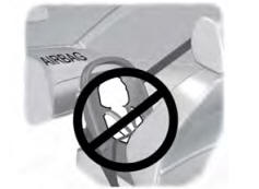
WARNING: Airbags can kill or injure a child in a child restraint. Never
place a rear-facing child restraint in front of an active airbag. If you must use
a forward-facing child restraint in the front seat, move the seat upon which the
child restraint is installed all the way back.
read more
.jpg)
.jpg)
.jpg)
.jpg)
.jpg)
.jpg)
.jpg)
.jpg)
.jpg)
.jpg)
.jpg)
.jpg)
.jpg)
.jpg)
.jpg)
.jpg)
.jpg)
.jpg)
.jpg)
.jpg)
.jpg)
.jpg)
 Removal and Installation - Timing Chain Tensioner
 Removal and Installation - Valve Tappets