
Ford Explorer: Steering Column / Removal and Installation - Steering Column Upper Shaft
Ford Explorer 2020-2026 Service Manual / Chassis / Steering System / Steering Column / Removal and Installation - Steering Column Upper Shaft
Removal
NOTE: Removal steps in this procedure may contain installation details.
-
Remove the steering column.
Refer to: Steering Column (211-04 Steering Column, Removal and Installation).
-
.jpg) WARNING:
Do not reuse steering column shaft bolts. This may
result in fastener failure and steering column shaft detachment or loss
of steering control. Failure to follow this instruction may result in
serious injury to vehicle occupant(s).
WARNING:
Do not reuse steering column shaft bolts. This may
result in fastener failure and steering column shaft detachment or loss
of steering control. Failure to follow this instruction may result in
serious injury to vehicle occupant(s).
-
Remove and discard the steering column shaft bolt.
-
Separate the steering column lower shaft coupler from the steering column upper shaft.
Torque: 35 lb.ft (48 Nm)
-
Remove and discard the steering column shaft bolt.
.jpg) |
-
Remove the steering column upper shaft.
.jpg) |
Installation
-
To install, reverse the removal procedure.
 Removal and Installation - Steering Column Opening Seal
Removal
NOTE:
Removal steps in this procedure may contain installation details.
Remove the steering column upper shaft.
Refer to: Steering Column Upper Shaft (211-04 Steering Column, Re..
 Removal and Installation - Steering Column Tilt Motor
Removal
NOTE:
Removal steps in this procedure may contain installation details.
Remove the steering column.
Refer to: Steering Column (211-04 Steering Column, Removal and Installation)...
Other information:
Ford Explorer 2020-2026 Service Manual: Removal and Installation - Rear Brake Flexible Hose
Removal WARNING: Service actions on vehicles equipped with electronic brake booster and electronic parking brakes may cause unexpected brake application, which could result in injury to hands or fingers. Put the brake system into service mode prior to servicing or removing any brake components...
Ford Explorer 2020-2026 Service Manual: General Procedures - Module Programming
Check NOTE: Perform the following pre-checks to make sure module programming completes without errors. Start the programming session in KOEO. Make sure the vehicle battery is fully charged or is connected to a battery charger. The battery state of charge should be 12...
Categories
- Manuals Home
- 6th Generation Explorer Owners Manual
- 6th Generation Explorer Service Manual
- General Procedures - Rear Camber Adjustment
- Body and Paint
- Automatic Transmission - 10-Speed Automatic Transmission – 10R60
- New on site
- Most important about car
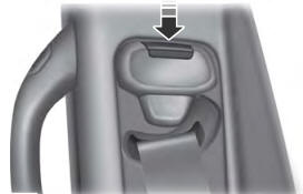
Seatbelt Height Adjustment
WARNING: Position the seatbelt height adjuster so that the seatbelt rests across the middle of your shoulder. Failure to adjust the seatbelt correctly could reduce its effectiveness and increase the risk of injury in a crash.

Copyright © 2026 www.foexplorer.com