Ford Explorer: Second Row Seats / Removal and Installation - Second Row Seat Backrest Blower Motor
Ford Explorer 2020-2025 Service Manual / Body and Paint / Body and Paint / Second Row Seats / Removal and Installation - Second Row Seat Backrest Blower Motor
Removal
NOTE: Removal steps in this procedure may contain installation details.
NOTE: LH (left hand) shown, RH (right hand) similar.
-
Remove the second row single seat backrest cover.
Refer to: Second Row Single Seat Backrest Cover - Vehicles With: Second Row Captain Chairs (501-10B Second Row Seats, Removal and Installation).
-
Disconnect the second row seat backrest blower motor electrical connector.
.jpg) |
-
Remove the second row seat backrest blower motor screws.
Torque: 71 lb.in (8 Nm)
.jpg) |
-
Remove the second row seat backrest blower motor.
-
Release the second row seat backrest blower motor clips.
-
Remove the second row seat backrest blower motor.
-
Release the second row seat backrest blower motor clips.
.jpg) |
Installation
-
To install, reverse the removal procedure.
 Removal and Installation - Second Row Seat Armrest
Special Tool(s) /
General Equipment
Interior Trim Remover
Removal
NOTE:
Removal steps in this procedure may contain installation details...
 Removal and Installation - Second Row Seat Climate Control Module
Removal
NOTE:
Removal steps in this procedure may contain installation details.
NOTE:
The SCMF (second row seat climate control module) is located
under the RH (right-hand) second row seat cu..
Other information:
Ford Explorer 2020-2025 Service Manual: Removal and Installation - Driveshaft Flexible Coupling
Removal NOTE: The maximum articulation of the flex coupling is 4 degrees. The maximum articulation of any U-joint is 25 degrees. The maximum articulation of the center CV-joint is 20 degrees. The maximum articulation of the rear axle CV-joint is 15 degrees...
Ford Explorer 2020-2025 Service Manual: Removal and Installation - Rear Parking Aid Camera Washer Jet
Removal NOTE: Removal steps in this procedure may contain installation details. Remove the rear parking aid camera. Refer to: Rear Parking Aid Camera (413-13B Parking Aid - Vehicles With: Parking Aid Camera, Removal and Installation). Disconnect the rear parking aid camera washer jet hose...
Categories
- Manuals Home
- 6th Generation Explorer Owners Manual
- 6th Generation Explorer Service Manual
- Fuel Filler Funnel Location & Running Out of Fuel
- Traction Control
- Body and Paint
- New on site
- Most important about car
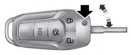
Integrated Keyhead Transmitter (If Equipped)
Use the key blade to start your vehicle and unlock or lock the driver door from outside your vehicle. The integrated keyhead transmitter functions as a programmed ignition key that operates all the locks and starts your vehicle, as well as a remote control.
Copyright © 2025 www.foexplorer.com